Identifying and Managing Sinks
July, 2020
Download the PDF here
Introduction
Arc Hydro consists of a data model, toolset, and workflows developed over the years to support specific geographic information system (GIS) implementations in water resources. The initial implementation of Arc Hydro was in 2002 with the data model, Arc Hydro book published by Esri Press, and an initial set of about 30 tools. Since then, Arc Hydro has been used in many projects, and in the process, new tools and workflows have been developed. There are now more than 300 Arc Hydro tools, and they continue to be expanded based on work in specific implementations.
This document describes key steps for using Arc Hydro tools for identification and processing of sinks. Sinks are a critical component of deranged and combined terrain representation in Arc Hydro. Initial release of Arc Hydro supported only fully dendritic terrain representation and did not explicitly discuss or have tools for sink processing. The initial capabilities for sink processing were added soon after the first release of Arc Hydro, in the 2003-2005 timeframe. Additional capabilities have been added over the years and this is an active area of Arc Hydro tools development.
Document history
Table 1. Document revision history
| Version | Description | Date |
|---|---|---|
| 1 | First version (DD) | 7/2020 |
Recommended reading
This is one of several Arc Hydro "How To" documents. In order of importance, users are encouraged to read the following accompanying documents:
Arc Hydro - Project Development Best Practices (both 10.x and Pro)
Arc Hydro - ArcGIS Pro Project Startup Best Practices (Pro only)
Arc Hydro - Overview of Terrain Preprocessing Workflows (referenced later in this document)
Arc Hydro - Wetland Identification Toolset (referenced later in this document)
Key definitions and sink processing overview
Sinks represent important geomorphological terrain structures. There are many definitions of "sinks". In this document, sinks are defined as depressions in the terrain that are lower than all neighboring terrain cells (or contours). Corollary of this definition is that sinks stop flow tracing over the landscape, either at the sink boundary or sink center. Lakes are different from sinks as they have a river that drains the lake extent while sinks do not. Moreover, wetlands can be represented as sinks or lakes. Here, we analyze sinks in the context of raster representation of the elevation models (DEM).
Sinks are often subjective and can be a function of the analyses being performed. For example, in flooding analyses, sinks are often ignored as it is expected that they will eventually fill, and water will flow through them, so while they are morphologically "sinks", they are not hydrologically. Even in flood analyses, removing sinks might not be the correct approach, as some sinks have large storage area and volume and ignoring those characteristics can skew hydrologic response of the area being analyzed.
Arc Hydro database design and tools have a suite of methods to manage sinks. Due to the somewhat subjective nature of the sinks, the analyst must be closely involved in the processing and make decisions based on the type of the analyses and terrain of interest.
There are three key steps in sink processing:
Sink identification. This step facilitates identification of which depressions in the terrain representation are "true" sinks, and which are "false" sinks that do not have to be represented as such and can be removed from the elevation model.
Sink preprocessing. This step removes "false" sinks from the elevation model, while keeping "true" ones and develops terrain derivatives (primarily hydro enforced flow direction).
Sink connectivity and characterization. This step connects sinks into the larger drainage system (connectivity) - this can be either fully deranged morphology where there are no rivers, just a collection of interconnected sinks, or combined morphology, where there is a mix of sinks and rivers. Sink characteristics define sink properties (e.g., stage-area-volume table and/or sink catchments, etc.). These characteristics allow inclusion of sinks into further hydrologic and hydraulic analyses.
Each of these steps is a sequence of operations - a workflow. Not all these steps need to be executed, depending on the goal of the analysis and available input data.
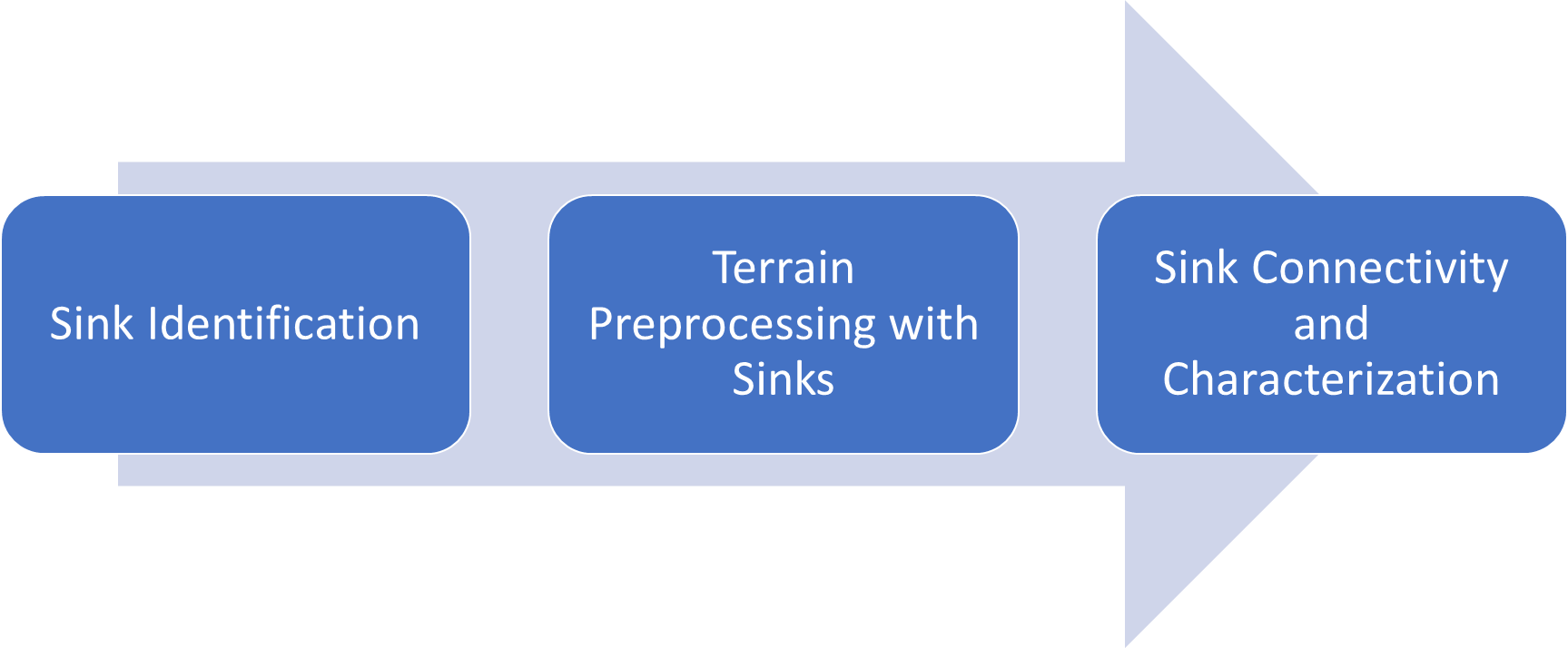
Figure 1. Sink processing key steps. Each of these steps represents a sequence of operations - a workflow.
In general, this is a linear process. Sinks first must be identified, then preprocessed, and then finally used in development of connectivity and for characterization. But this can also be a circular process where the analyst will modify earlier decisions based on the results of the later ones (primarily selection of "true" sink polygons as that decision propagates through all later steps).
An optional step that can be applied before sink identification is DEM pre-conditioning. This is a general step used to condition the "raw" DEM before further analyses are done. The goal of this step is to remove "noise" in the DEM. Some of the tools described in this document have that capability built in, but pre-conditioning can be done regardless. While pre-conditioning can have significant impact on the performance of the tools and quality of the results, it does not impact the sequence of operations and will not be discussed further in this document.
Arc Hydro database design has specific feature classes and attributes that are extensively used throughout sink processing. These are all "standard" Arc Hydro database elements. In particular:
HydroID - unique global integer identifier for every feature within the Arc Hydro geodatabase.
SinkID - HydroID of the sink point.
DrainID - HydroID of the drainage area.
IsSink - integer attribute identifying if a polygon is a sink feature (=1) or not (=0 or <null>).
Solution overview
While the screen captures are based on the ArcMap version of Arc Hydro tools, this document is not focused on a specific version of ArcGIS or Arc Hydro - it is a workflow that transcends specific versions. The tools discussed in this document have been part of the Arc Hydro 10.x platform (and earlier) for many years and are in the Arc Hydro Tools Pro toolbox supporting ArcGIS Pro 2.4 and later. There are no differences in behavior or functionality between versions of the tools.
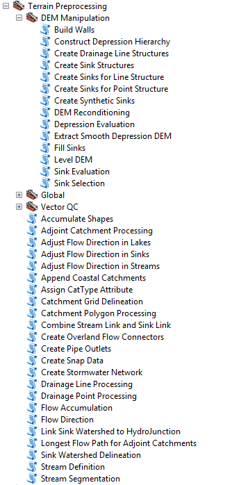
Sink processing, as part of terrain processing capabilities, is implemented through many Arc Hydro tools organized in several toolsets. Table below presents the four toolsets containing relevant sink processing tools.
Table 2. Arc Hydro toolsets involved in sink processing (Arc Hydro Tools Python toolbox).
 |  |
|---|---|
 | |
 |
Overview of Arc Hydro tools involved in sink processing
This section presents a list of tools used in sink processing. Tools in this section are presented in the order they appear in the Arc Hydro Tools Python Toolbox and do not represent the order in which tools are used. Not all the tools are used in all situations. The subsequent sections will explore specific workflows and which tools are used for them.
Table 3. Overview of Arc Hydro tools involved in sink processing.
| Toolset | Step | Tool | Description |
|---|---|---|---|
| Point Characterization | Connectivity and characterization | Generate Point Connectivity | Generate connectivity and watersheds associated to input point features. |
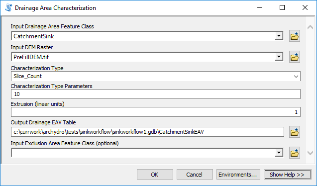
| Terrain Morphology / Drainage Boundary Processing | Connectivity and characterization | Drainage Area Characterization | The Drainage Area Characterization tool (Terrain Morphology toolset) generates elevation, area and volume curves for a set of selected drainage areas. The function divides each drainage area into slices and calculates each slice's elevation characteristics, as well as the cumulative area and volume that are below the elevation of the top of the slice. These characteristics are stored in an output Drainage EAV table. The function works with a selected set of drainage areas or with all drainage areas within the input feature class if there is no selected set. |
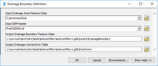
| Connectivity and characterization | Drainage Boundary Definition | Generates 3D boundaries lines for the polygon features in the input Drainage Area feature class and stores these lines in the output Drainage Boundary 3D polyline feature class (Zs are stored in linear unit of the terrain). Stores in the output Drainage Connectivity table the HydroID of each boundary lines together with the HydroIDs of the 2 drainage areas it separates. | |
| Connectivity and characterization | Drainage Connectivity Characterization | Generates connectivity for deranged terrain through the lowest elevations on the boundaries. | |
| Terrain Preprocessing | Preprocessing | Adjust Flow Direction in Sinks | Adjust Flow Direction in Sinks so that water drains into one unique sink point location in each sink polygon. |
| Preprocessing | Combine Stream Link and Sink Link | Generates the combined link grid representing both dendritic and deranged terrains. | |
| Preprocessing | Link Sink Watershed to HydroJunction | Populate JunctionID field in SinkWatershed with HydroID of HydroJunction used in the StormWater network as Sinks/INlets. | |
| Preprocessing | Sink Watershed Delineation | Delineate watersheds for sinks. Create both raster and vecort representation of the watershed. | |
| Terrain Preprocessing / DEM Manipulation | Preprocessing | Build Walls | Creates a DEM grid with external and/or internal walls burnt in, except at the location of the breach lines. |
| Identification | Construct Depression Hierarchy | Identifies closed contours in the DEM, their nested structure, and defines attributes identifying "position" of the contour within the nested contour structure. Several criteria are used to define the closed contours. | |
| Preprocessing | Create Sink Structures | Define correctly Arc Hydro configured sink point and polygon feature classes and grids based on input deranged polygon and reference DEM. | |
| Preprocessing | Create Sinks for Line Structure | Create Sink polygons and sink points at the beginning of the lines of type structure. | |
| Preprocessing | Create Sinks for Point Structure | Create Sink polygons and sink points at the location of input point structures associated to from point of lines. | |
| Preprocessing | Create Synthetic Sinks | Create Sink polygons at the end specified input line features (e.g. sink feed stream features with no associated sink polygon). | |
| Identification | Depression Evaluation | Identify potential depressions. | |
| Identification | Extract Smooth Depression DEM | Identifies areas within DEM that fall within potential depressions (areas draining into sinks). The result is a raster with "smoothed" DEM in the depression areas and "no data" elsewhere. | |
| Preprocessing | Fill Sinks | Fill sinks in input DEM. | |
| Preprocessing | Level DEM | Levels the DEM by filling the Lake polygons up to their FillElev - offset value | |
| Identification | Sink Evaluation | Identify potential sinks. | |
| Identification | Sink Prescreening | Prefill sinks not meeting minimum drainage area criteria. | |
| Identification | Sink Selection | Populate field IsSink with 1 based on specified criteria. | |
| Terrain Preprocessing Workflows / Combined | Preprocessing | Combined Terrain with Unknown Sink and Stream Locations | Combined dendritic/deranged terrain with unknown initial sink and stream locations. Stream defined using 1% of maximum flow accumulation. |
| Terrain Preprocessing Workflows / Deranged | Preprocessing | Basic Deranged Terrain Processing | Completely deranged terrain with unknown sink location and no filling of sinks. |
| Preprocessing | Deranged Terrain with Known Sink Location and Some Filling | Completely deranged terrain with known sink location and some filling of sinks (always need filling when not keeping all sinks). | |
| Preprocessing | Deranged Terrain with Unknown Sink Location and No Filling | Completely deranged terrain with unknown sink location and no filling of sinks. |
Sink identification
This section presents tools for sink identification and definition. Two methods are described:
Sink evaluation.
Contour.
Identification of sinks as wetlands is also possible. Review "Arc Hydro
- Wetland Identification Toolset" for detailed presentation of tools and techniques for wetlands identification using machine learning approach. This toolset is available only in Pro version of Arc Hydro. Note that for this approach you need to have a training dataset (set of known wetland polygons) that can be used to train the machine learning algorithm used in the toolset.
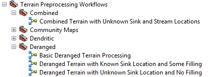
Approach 1 - sink evaluation method
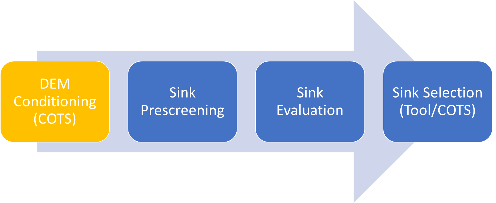
Figure 2. Overview of sink evaluation method.
The following steps are performed when following sink evaluation method (DEM conditioning is optional):
Sink prescreening. Prefill sinks not meeting minimum drainage area criteria provided by the user.
Sink evaluation. Identify and characterize sinks by calculating their area, depth, volume and contributing area.
Sink selection. Select sinks based on the sink properties calculated in step 2 (or using any other selection method).
Sink prescreening
This step eliminates those sinks whose drainage area is not large enough to be considered for further analyses, as defined by the user as an input parameter. This is an optional step. If not performed, all depressions will be considered as potential sinks in further steps. The idea is to use as large an area as possible without jeopardizing later capability to select sinks. If in doubt, use a smaller area (or completely skip this step) as later processing will allow additional sink elimination. Use of this step can significantly improve performance of later steps though, so it is recommended.
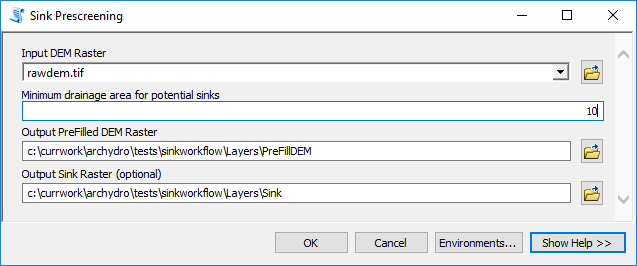
See appendix for tool run results.
Sink evaluation
Sink evaluation generates the following two feature classes and key attributes:
SinkPoly - polygon feature class with "draft" sink polygons.
HydroID - unique integer identifier.
DrainID - HydroID of the drainage area (from SinkDA feature class) draining into the sink.
BottomElev - elevation of the bottom of the sink.
FillElev - elevation at which the sink will "spill" (to which it will be filled).
FillDepth - depth that the sink will be filled.
FillArea - area that will be filled.
Fillvolume - volume that will be filled.
DrainArea - area draining into the sink.
IsSink - indicator defining if a polygon should be treated as a sink (=1) or not (=0). By default, all the values are set to 0 initially.
SinkDA - polygon feature class with drainage areas draining to "draft" sink polygons.
- HydroID - unique integer identifier.
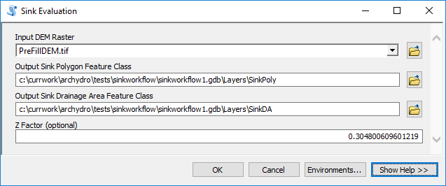
See appendix for tool run results.
Notice that by default, none of the identified sink polygons are labeled as "sinks" (IsSink=0). The following step is intended to provide the user that capability.
Sink selection
This is an optional step in which "draft" sinks can be selected and defined as "real" sinks for later analyses. While there is a specific Arc Hydro tool to help with sink selection, any selection (or combination of) can be used to select sink polygons of interest, and then setting their IsSink attribute to 1 (using field calculate).
In the following example, only sinks whose area is greater than 300,000 are defined as "real" sinks. That will select only 14 out of 808,049 "draft" sinks and tag them as "real" sinks.
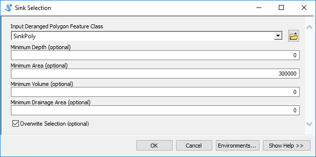
See appendix for tool run results.
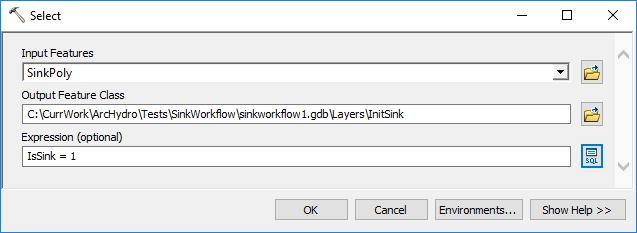
Once "real" sinks are selected (and IsSink field is set to 1), these sinks can be extracted into a separate feature class. This can be useful if the decision about the "real" sinks is definitive and further review is not necessary. Creating a dedicated "real" sink feature class can make operations faster (smaller polygon feature class to operate on) and less dependent on IsSink field being correctly populated. This is especially the case if non-Arc Hydro tools will also be used in the overall analyses that natively do not support use of the IsSink field.
In this exercise, a feature class "InitSink" will be created with 14 selected sink polygons.
Approach 2 - contour tree method
This approach is based on work by Dr.Qiusheng Wu (Wu Q., Liu H., Wang S., Yu B., Beck R., Hinkel K., 2015. A localized contour tree method for deriving geometric and topological properties of complex surface depressions based on high-resolution topographical data. International Journal of Geographical Information Science, 29 (12), 2041-2060. doi/full/10.1080/13658816.2015.1038719).
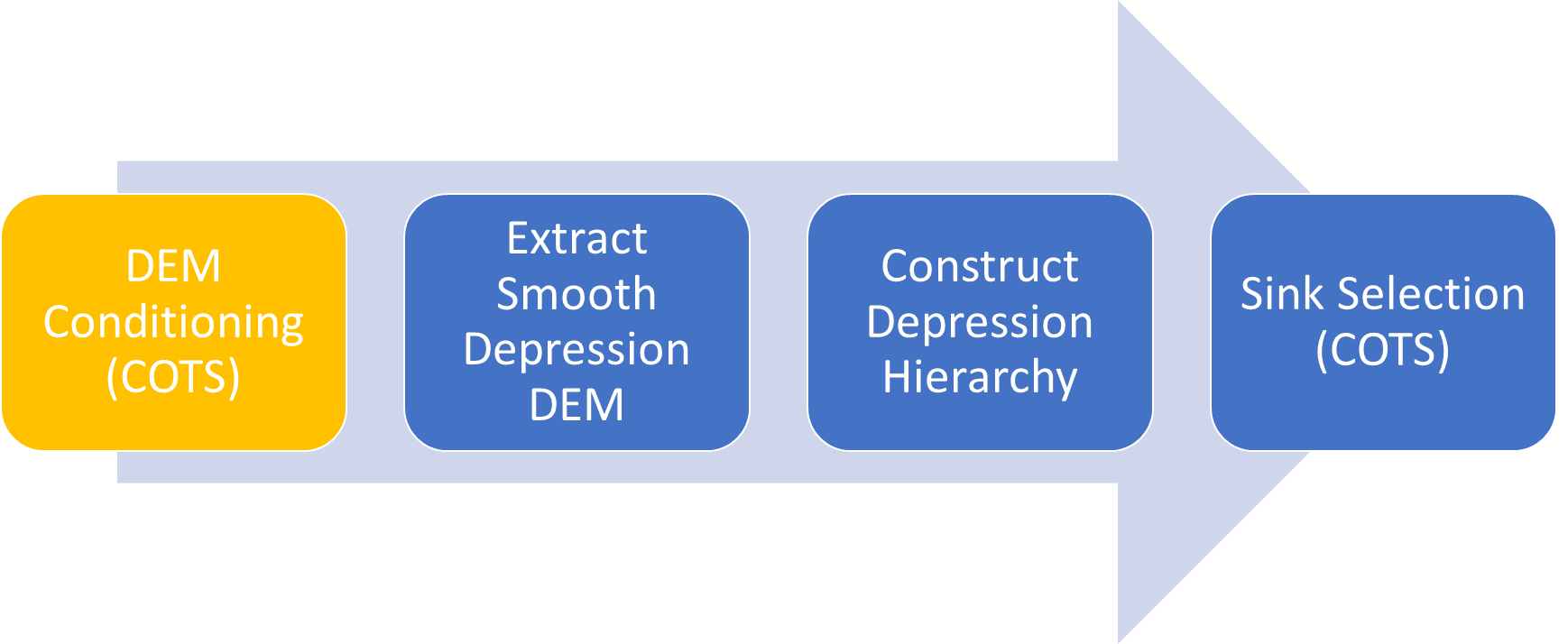
Figure 3. Overview of contour tree method.
The following steps are performed when following contour tree method (DEM conditioning is optional):
Extract smooth depression DEM. This is an optional, but highly recommended step. It will significantly improve performance and quality of resulting contours developed in the following function.
Construct depression hierarchy.
Sink selection (using conventional out-of-the-box ArcGIS selection).
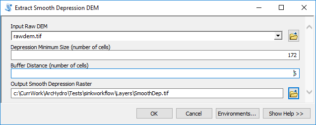
Extract smooth depression DEM
This tool identifies areas within DEM that fall within potential depressions (areas draining into sinks). The tool also applies a 3 by 3 cell "mean" filter, which reduces variability in the elevation values and removes small imperfections. The result is a raster with "smoothed" DEM in the depression areas and "no data" elsewhere. Use of this raster as input in the next step will produce better looking contours with little sacrifice in quality of results. Notice use of:
172 cells as depression's minimal area (~16 m2).
6 cells as buffer distance (~1.8 m). This is used as a buffer around sink polygons when extracting the smooth DEM.
These parameters are user specified. Increasing the number of cells defining the depression minimum size will eliminate more sinks and will results in a smaller smooth DEM resulting in faster later processing.
See appendix for tool run results.
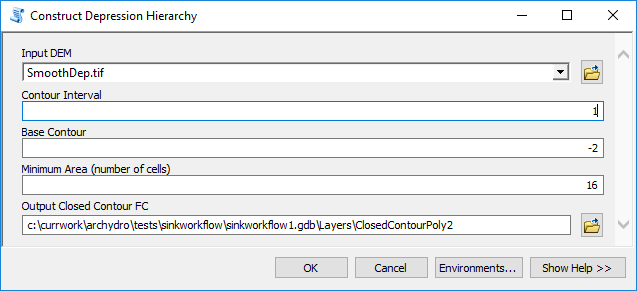
Construct depression hierarchy
This tool identifies closed contours in the DEM, their nested structure, and defines attributes identifying "position" of the contour within the nested contour structure. The key attributes that will be populated for each nested contour polygon are:
HydroID - unique feature identifier
Contour - contour elevation
ROOTID - HydroID of the root contour containing current contour (top contour polygon for depressions and bottom for hills).
PID - HydroID of the immediate contour containing the current contour.
SINKLEVEL - sequence of the nested contour in the contour nest. Negative number indicates "terminal" contour (there are no other contours within it).
Using these attributes, it is possible to determine the relationship between different contour polygons for further analyses and guide the selection of "real" sinks.
See appendix for tool run results.
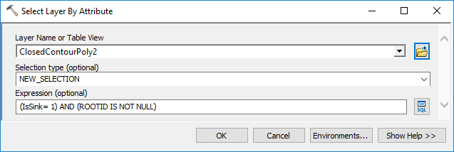
Sink selection
The "Construct depression hierarchy" tool will populate IsSink field in the output polygon feature class with value of 1 for those contour polygons that are the lowest within a depression contour nest. It is possible that multiple contour polygons within the same depression nest will be identified. It is also possible that not all polygons identified with this tool are to be used as sinks based on other selection criteria.
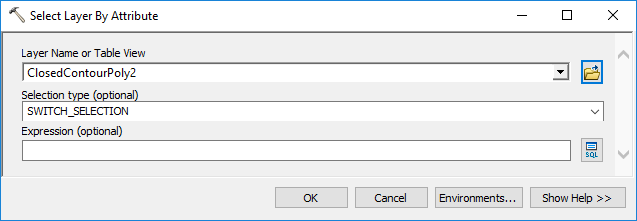
Sink polygon selection can be made using standard ArcGIS selection tools. In the following example, a new field called "IsSink1" is created first and the final sink selection will have it set to 1. Following are some examples of the type of additional selection that can be made:
Selecting the smallest, lowest contour polygon within a single contour nest. This can be done using ROOTID as the main container and initial IsSink classification.
- Select IsSink contours that are not single sink contours.
- Calculate minimal area for contour polygons within a contour nest. Note that the resulting table will have attribute "FREQUENCY" that will identify how many contour polygons within each individual contour nest. In general, all polygons with FREQUENCY = 1 indicate that there is only one "lowest" contour within the nest and could be ignored in later processing but keeping them in does not affect the following steps and keeps the process simpler.

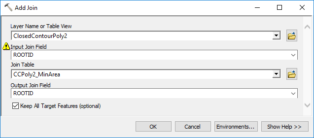
- Join statistics and feature class tables using ROOTID as key.
- Select the lowest minimal contour per contour nest and remove join.


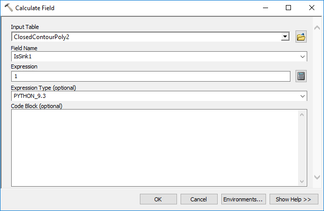
- Calculate "IsSink1" field.
Similar process could be applied for finding the largest, lowest contour polygon within a single contour nest or a "deepest" one (by doing a zonal stats on the DEM with minimum option for each lowest contour to get the depth and then pick the deepest one).
Selecting only contour polygons larger than a specific area threshold.
Any other selection criteria.
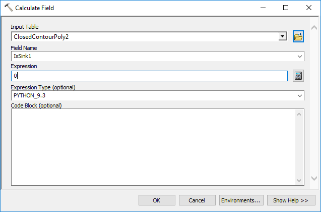
Once the selection is made, field IsSink should be calculated as 1 and all other contour polygons should have their IsSink field calculated as 0 (do not forget to do the latter step).
Terrain preprocessing with sinks
After sink polygons have been determined (also referred to as "deranged" polygons), there are different ways to incorporate them into standard Arc Hydro terrain processing. Arc Hydro document "Arc Hydro - Overview of Terrain Preprocessing Workflows" presents an overview of different terrain morphologies and their processing using Arc Hydro tools. The following table is from that document and presents different use cases as a function of terrain morphology and available input data.
Table 4. Overview of terrain processing use cases/workflows from "Arc Hydro - Overview of Terrain Preprocessing Workflows" document.
| Terrain morphology | Deranged only | Combined | Dendritic only |
|---|---|---|---|
| DEM only (no stream or sink information) | Use case 1 Use case 2 | Use case 4 | Use case 7 |
| DEM and known sinks | Use case 3 | ||
| DEM and known streams and sinks | Use case 5 Use case 6 | ||
| DEM and known streams | Use case 8 Use case 9 |
Terrains that have sinks fall under one of the following categories:
Completely Deranged Terrain - has only sinks and no streams. This is covered in use cases 1-3.
Combined Dendritic/Deranged Terrain - has both sinks and streams. This is covered in use cases 4-6.
In this document we present a simplified use case 3 - "Completely Deranged Terrain with Known Sink Location", using sinks identified in section 3.1.3 as "known sink location". For other use cases, refer to the "Arc Hydro - Overview of Terrain Preprocessing Workflows" document.
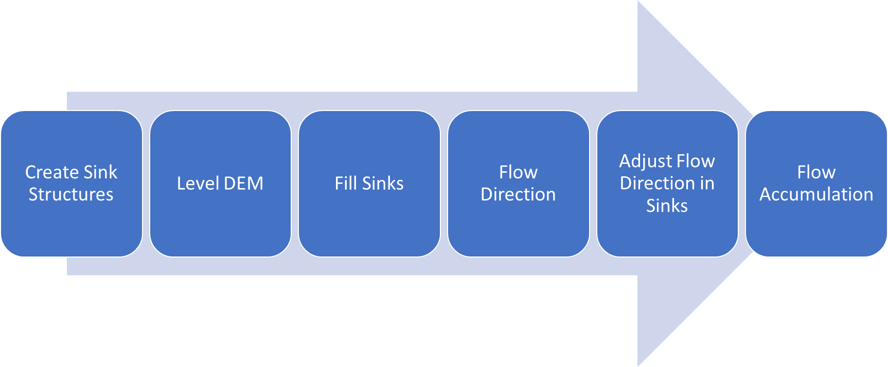
Figure 4. Key steps in terrain preprocessing for completely deranged terrain with known sink polygons.
Steps after sink polygons have been determined:
Create sink structures.
Level DEM (optional). Presented and discussed in this document.
Fill sink.
Flow direction.
Adjust flow direction in sinks.
Flow accumulation.
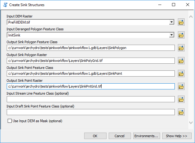
Create sink structures
Create sink structures generates vector and raster representation of the sink polygon and sink point (one point per polygon) that are consistent with the underlying DEM (same cell size, extent, and snapping raster). These constructs, instead of the original input sink polygons, are then used in later processing to ensure vector/raster consistency of the operations. This step is particularly important if the input sink polygons were brought in from other GIS sources (e.g. heads-up digitized or derived from a different resolution DEM).
See appendix for tool run results.
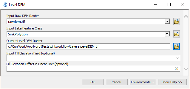
Level DEM
This step should be used when the "deranged" polygon layer (one with known sinks) is coming from a vector background (e.g. digitized polys or ones derived from the contour method). This step "pushes" the elevation cells within and on the boundary of the sink polygons down and ensures that there are no boundary or localized sink effects before filling sinks.
This is an optional step but is presented here for consistency. It should be used if the sink polygons are brought in from vector sources or derived from a different DEM source.
Notice use of:
Raw DEM as input DEM (although it could be the prefilled one - depending on the sink identification method used).
Leaving optional "Fill Elevation Field" empty. That will force calculation of "FillElev" field first (minimal elevation along the boundary of the sink polygon) and then field "LevelElev" will be calculated by subtracting the offset value from the fill elev value. "LevelElev" will then be internally used to level the dem within each sink polygon. Alternatively, this field can be created manually and populated with a fixed number that will ensure that those elevations are always lower than any of the surrounding sink polygon boundary cells across ALL sink polys. This can reduce tool's execution time and makes sense when one number will fit the regional approach (usually when the topography is fairly uniform).
Positive value for "Fill Elevation Offset". This will push the calculated minimal boundary value (from FillElev field) DOWN. If a negative value is provided, that will RAISE the boundary value, basically extruding the elevation (could be used to build-up the buildings that were removed from the bare earth DEM).
See appendix for tool run results.
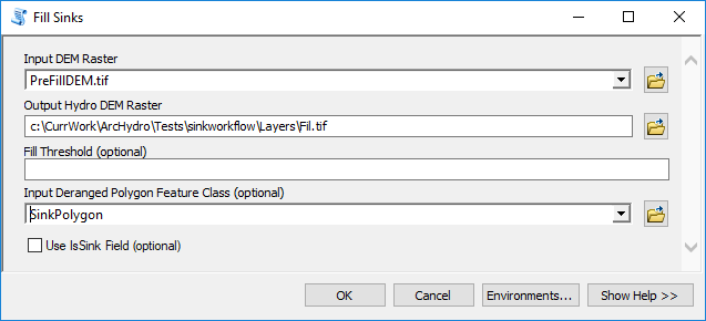
Fill sinks
Filling sinks with provided "deranged polygon" feature class will fill sinks in the DEM, EXCEPT in the deranged polygons, thus keeping them as sinks. From the parameters, notice:
Prefilled DEM as input DEM.
Use of result of "Create sink structures" - SinkPolygon feature class - as input deranged polygon feature class.
No use of "Fill Threshold".
No use of "Use IsSink Field".
See appendix for tool run results.
Flow direction
Notice use of:
- Filled DEM as input DEM.
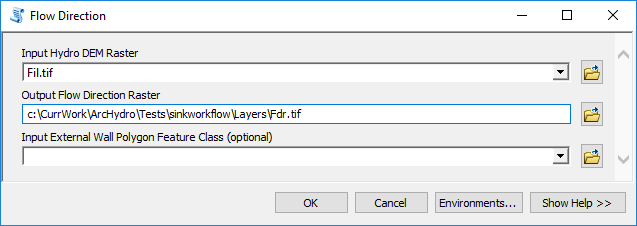
See appendix for tool run results. The resulting flow direction will stop at the deranged polygon boundary (will be undetermined within the deranged polygons).
Adjust flow direction in sinks
This function will define the flow direction within the deranged polygons to flow into the sink point. Notice use of:
- Use of results from "Create sink structures" as inputs for sink point and polygon rasters.
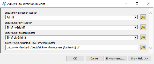
See appendix for tool run results.
Flow accumulation
Notice use of:
- Use of sink adjusted flow direction as input. This will guarantee that the flow accumulation will extend into the sink point instead stopping at the sink polygon boundary.
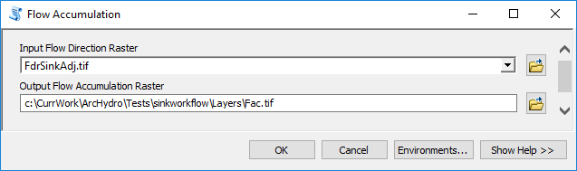
See appendix for tool run results.
Sink connectivity and characterization
To complete the representation of deranged morphology, individual sinks can be connected and characterized. Not all the steps presented here are required - it all depends on the ultimate goal of the analysis.
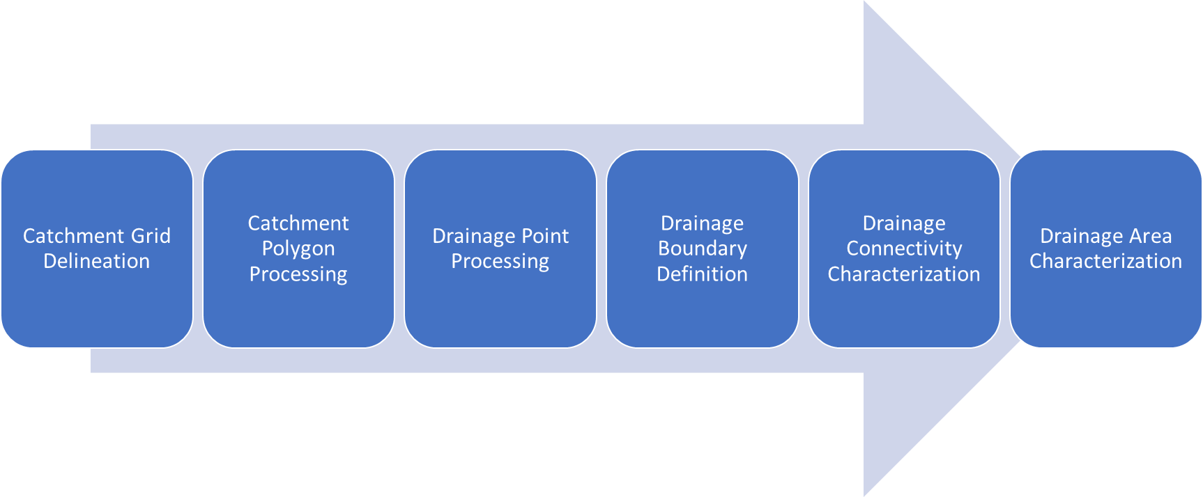
Figure 5. Key steps in sink connectivity and characterization.
Steps for establishing connectivity and sink characterization after initial terrain preprocessing has been completed:
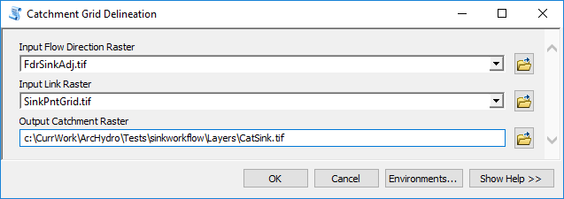
Catchment grid delineation. Identifies drainage areas draining into sinks in raster format.
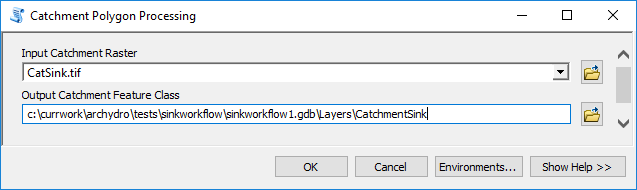
Catchment polygon processing. Identifies drainage areas draining into sinks in vector format.
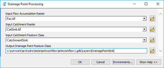
Drainage point processing. Identifies drainage points (points with maximum flow accumulation within a catchment). For fully deranged terrains (as presented in this document), drainage points will match sink points, but in a combined morphology, there will be additional drainage points related to catchments draining to drainage lines (streams).
Drainage boundary definition. Identifies boundaries between catchments.
Drainage connectivity characterization. Identifies connectivity between drainage areas within the system.
Drainage area characterization. Calculates stage-area-volume curves for drainage areas (could be for any polygon feature class).
Figure below shows some of the drainage structures that are created once the steps are executed. This is a zoomed in figure on two connected sinks. Depending on the sink selection decision (how many of the initially identified DEM sinks are kept as "true" sinks), and type of the terrain preprocessing (here, only fully deranged workflow was executed - there are no rivers connecting the sink areas), the resulting landscape representation could look significantly different.

Figure 6. Example of sink elements created during sink processing.
In the figure:
Blue-filled polygons represent "true" sink polygons (ones selected by the user).
Red polygons represent drainage areas for sinks (catchments/sink watersheds).
Red dots represent hydro junctions - points on the network connecting hydro elements.
Points on the watershed boundaries are placed on the lowest point along the boundary between the two sink watersheds
Points within the sink polygon are placed at the sink point.
Blue lines represent hydro edges - links on the network connecting hydro elements. These are sink connectors, and in combined morphology with streams, also streams.
For terrain morphology with streams (combined workflow), the junctions on sink boundaries would be connected to the streams with hydro edges.
Catchment grid delineation
Notice use of:
- Sink point raster as input link raster.
See appendix for tool run results.
- Catchment polygon processing
See appendix for tool run results.
Drainage point processing
See appendix for tool run results.
Drainage boundary definition
See appendix for tool run results.
Drainage connectivity characterization

See appendix for tool run results.
Drainage area characterization
See appendix for tool run results.
Appendix 1: Performance results
Test dataset
The sample raster DEM used for performance review is an 8,000 by 6,000 cell, floating point raster with 5ft cell size and elevation in ft (NAD_1983_2011_StatePlane_Florida_West_FIPS_0902_Ft_US; NAVD_88). Raster was derived from Lidar survey. Data are located in Manatee River watershed in southwest Florida (Mill Creek). Data were provided courtesy of Southwest Florida Water Management District.
Results overview
The information in this appendix is provided for reference only. The actual performance will vary greatly depending on the size and complexity (number of sinks) of the underlying DEM, function parameters, and sink selection criteria. The numbers provided here are to be used as a relative measure of performance - which functions are "faster" and which are "slower". Remember that raster processing tends to be non-linear for large rasters and that doubling the size of the raster will usually result in more then doubling the time it takes to process it.
The presented results are based on a single run of the tool on a machine that was not dedicated just to performance testing, so random system activities could also have affected execution times. ArcMap and Pro versions of AH tools were run on the same machine.
The hardware used for processing will also have an impact on the performance. Fast hard-drive (HD) subsystem (preferably SSD) can double the improvement in performance compared to traditional HD. Make sure that both the scratch and permanent storage are pointing to the fast HD.
Processing described in this document generates a lot of new raster products, some temporary, some permanent. For large DEMs, this can fill up the HD space quickly. At minimum, you should have at least 10 times the available storage as the size of the input DEM. Preferably, 20-50 times. For other processing suggestions, refer to "Arc Hydro - Project Development Best Practices" document.
Table 5. Tool execution times (times are rounded).
| Function | Execution time (10.7.1) | Execution Time (2.6.2) |
|---|---|---|
| Sink prescreening | 3' 40" | 3' |
| Sink evaluation | 18' 30" | 17' 0" |
| Sink selection | 50" | 4" |
| Extract smooth depression DEM | 2' 20" | 2' 50" |
| Construct depression hierarchy | 2h 0' 40" | |
| Create sink structures | 30" | 50" |
| Level DEM | 1' 30" | 1' 0" |
| Fill sinks | 1' 0" | 50" |
| Flow direction | 30" | 40" |
| Adjust flow direction in sinks | 40" | 40" |
| Flow accumulation | 50" | 1' 20" |
| Catchment grid delineation | 20" | 30" |
| Catchment polygon processing | 5" | 20" |
| Drainage point processing | 10" | 10" |
| Drainage boundary definition | 15" | 40" |
| Drainage connectivity characterization | 25" | 1' 20" |
| Drainage area characterization | 3' 20" | 6' 10" |
Appendix 2: Pro screenshots
This section has screenshots for tools run in Pro.
Table 6.Sink processing functions UI in Pro.
| Function | UI |
|---|---|
| Sink prescreening | 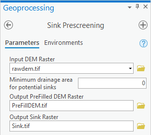 |
| Sink evaluation | 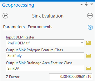 |
| Sink selection | 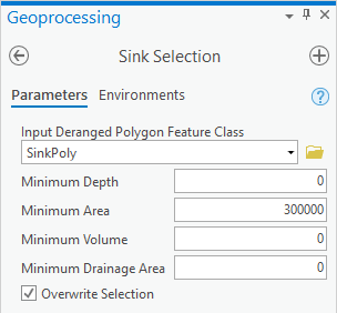 |
| Extract smooth depression DEM | 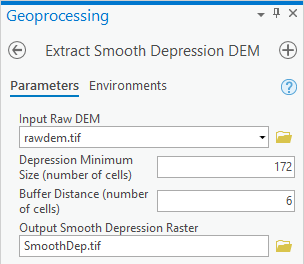 |
| Construct depression hierarchy | |
| Create sink structures | 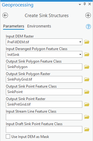 |
| Level DEM | 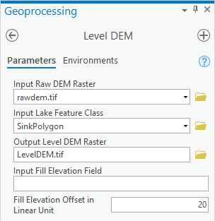 |
| Fill sinks | 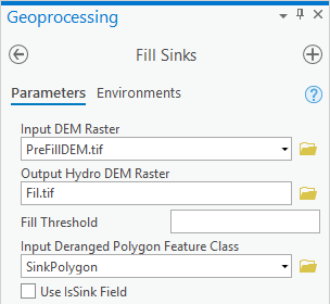 |
| Flow direction | 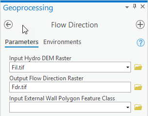 |
| Adjust flow direction in sinks | 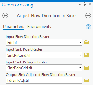 |
| Flow accumulation |  |
| Catchment grid delineation | 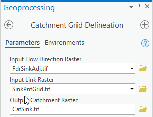 |
| Catchment polygon processing |  |
| Drainage point processing | 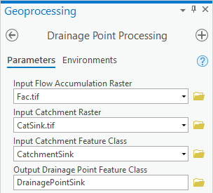 |
| Drainage boundary definition | 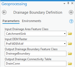 |
| Drainage connectivity characterization | 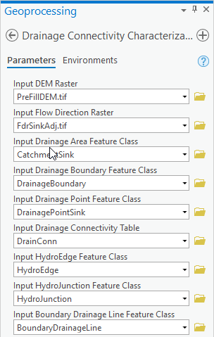 |
| Drainage area characterization | 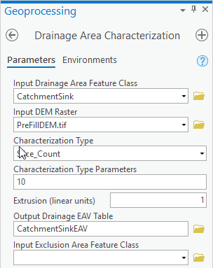 |
Appendix 3: Database design
The following key sink data elements are created during this workflow.
Table . Key database elements
| Name | Type | Description | Key fields |
|---|---|---|---|
| InitSink | Feature | Input deranged polygons. Can be coming from any source. |
|
| SinkPoint | Feature | "Center" of the sink polygon. |
|
| SinkPolygon | Feature | Sink polygon. Has "jagged" edges matching the resolution of the DEM. Derived from "deranged" polygons. |
|
| CatchmentSink | Feature | Catchment (watershed) for sink point/polygon. |
|
| SinkPntGrid | Raster | Sink point raster. | Value = SinkID/GridID/grid_code |
| SinkPolyGrid | Raster | Sink polygon raster. | Value = SinkID/GridID/grid_code |
| CatSink | Raster | Sink catchment raster. | Value = SinkID/GridID/grid_code |