Overview of Terrain Preprocessing Workflows
August, 2019
Download the PDF here
Introduction
Arc Hydro is a data model, toolset, and workflows developed over the years to support specific GIS implementations in water resources. The initial implementation of Arc Hydro was in 2002 with the data model, Arc Hydro book published by Esri Press, and initial set of about 30 tools. Since then, Arc Hydro has been used in many projects and in the process new tools and workflows have been developed. Arc Hydro tools now number in the 300s and continue to be expanded based on work on specific implementations.
This document describes key steps in Arc Hydro deranged, combined, and dendritic terrain preprocessing using Arc Hydro tools. The processing is organized into workflows based on the key geomorphologic characteristic of the terrain being processed. Approach taken in this document is to describe multiple use cases and which tools to use to generate "proper" results. Not all Arc Hydro terrain preprocessing tools are presented here, there are other tools that can be used in specific morphologies and processing requirements. The use cases presented here are the most commonly encountered ones.
While the screen captures are based on ArcMap product, this document is not focused on a specific version of ArcGIS or Arc Hydro - it is a set of generic recommendations that transcend specific versions.
Document history
Table 1. Document Revision History
| Version | Description | Date |
|---|---|---|
| 1 | First Version (DD) | 06/2012 |
| 2 | Major revisions (DD) | 03/2013 |
| 2.1 | Minor revisions (DD) | 01/2014 |
| 3 | Minor revisions, new "look", ArcGIS Pro reference (DD) | 08/2019 |
Solution Overview
Terrain preprocessing capabilities are implemented as many Arc Hydro tools organized in the "Terrain Preprocessing" toolset. Some of the basic tools described in this document are also present in the Arc Hydro Arc Map toolbar (but not in ArcGIS Pro Arc Hydro tools ribbon). When options are available, it is recommended that python version of the tools from the toolset is used.
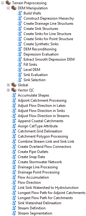
Figure 1. Arc Hydro "Terrain Preprocessing" toolbox/toolset (Arc Hydro Tools Python).
The original set of tools discussed in this document have been part of Arc Hydro 10.x platform since version 10.2.0.68. and are in the Arc Hydro Tools Pro toolbox supporting ArcGIS Pro 2.3.3 and higher. There is no difference in behavior or functionality between all versions of the tools. This document uses screenshots from the ArcMap version of the tools.
Overview of Arc Hydro Terrain Preprocessing Workflows
Geomorphologic (use case) terminology:
Completely deranged terrain. Contains only sinks. Streams are not represented in Arc Hydro.
Completely dendritic terrain. There are no sinks in the system, only streams.
Combined dendritic/deranged terrain. There are streams and sinks in the system. Streams can be independent from the sinks and/or flow into them.
There can be additional steps in terrain preprocessing that are not explicitly discussed in this document such as sink prescreening or walling, or data development steps such as "Create Sinks for Line Structure" or "Create Synthetic Sinks". These techniques/tools do not impact the order and tool capabilities presented in this document. These operations can be inserted into presented workflows with minimal impact. The placement though needs to be correct to obtain proper effect (e.g. first fence and then burn if you want the fenced area to flow out, or first burn and then fence if you do not want the area to flow out).
Table 2. Overview of terrain processing use cases/workflows.
| Deranged only | Combined | Dendritic only | |
|---|---|---|---|
| DEM only (no stream or sink information) | Use case 1 Use case 2 | Use case 4 | Use case 7 |
| DEM and known sinks | Use case 3 | ||
| DEM and known streams and sinks | Use case 5 Use case 6 | ||
| DEM and known streams | Use case 8 Use case 9 |
Note that the tools expect "clean" and consistent data. For example, streams that are to be burned in, must extend to the edge of the DEM or end in a sink, have to be snapped at confluences, and should be digitized in downstream direction.
The tools leverage existing Arc Hydro database design for feature identification and default layer naming. Due to the integrated nature of terrain preprocessing, the tools and data structures are designed to be closely tied together and executed in specific sequence.
Use Cases
Use case 1: Completely deranged terrain with unknown sink location and no filling of sinks
Sink Evaluation.
Create Sink Structures.
Flow Direction.
Adjust Flow Direction in Sinks.
Sink Watershed Delineation.
Append Coastal Catchments.
Assign CatType Attribute to Catchment FC (optional).
Use case 2: Completely deranged terrain with unknown sink location and some filling of sinks (always needs filling when not keeping all sinks)
Sink Evaluation.
Selection of sinks process (this is NOT an Arc Hydro tool but rather a process). Any technique for selecting sinks can be used. The end result is a "polygon" feature class with polygon features defining sink polys to keep as sinks.
Use Arc Hydro Sink Selection tool.
Interactively pick polys.
...
Create Sink Structures.
Fill Sinks.
Flow Direction.
Adjust Flow Direction in Sinks.
Sink Watershed Delineation.
Append Coastal Catchments.
Assign CatType Attribute to Catchment FC (optional).
Use case 3: Completely deranged terrain with known sink location and some filling of sinks (always needs filling when not keeping all sinks)
Create Sink Structures.
Level DEM.
Fill Sinks.
Flow Direction.
Adjust Flow Direction in Sinks.
Sink Watershed Delineation.
Append Coastal Catchments.
Assign CatType Attribute to Catchment FC (optional).
Use case 4: Combined dendritic/deranged terrain with unknown initial sink and stream locations
Sink Evaluation.
Selection of sinks process.
Create Sink Structures.
Fill Sinks.
Flow Direction.
Adjust Flow Direction in Sinks.
Adjust Flow Direction in Lakes. This is an optional step if there are lakes that are being drained by the streams (these are NOT sink lakes).
Sink Watershed Delineation.
Flow Accumulation.
Stream Definition.
Stream Segmentation.
Combine Stream Link and Sink Link.
Drainage Line Processing.
Catchment Grid Delineation.
Catchment Polygon Processing.
Adjoint Catchment Processing.
Append Coastal Catchments.
Assign CatType Attribute to Catchment FC (optional).
Use case 5: Combined dendritic/deranged terrain with known sink and stream locations (using synthetic streams)
Create Drainage Line Structures.
DEM Reconditioning.
Create Sink Structures.
Level DEM.
Fill Sinks.
Flow Direction.
Adjust Flow Direction in Sinks.
Adjust Flow Direction in Streams.
Adjust Flow Direction in Lakes (optional).
Sink Watershed Delineation.
Flow Accumulation.
Stream Definition.
Stream Segmentation.
Combine Stream Link and Sink Link
Drainage Line Processing (use combined Stream/Sink Link Grid as input).
Catchment Grid Delineation.
Catchment Polygon Processing.
Adjoint Catchment Processing.
Append Coastal Catchments.
Assign CatType Attribute to Catchment FC (optional).
Use case 6: Combined dendritic/deranged terrain with known sink and stream locations (using user specified streams)
Create Drainage Line Structures.
DEM Reconditioning.
Create Sink Structures.
Level DEM.
Fill Sinks.
Flow Direction.
Adjust Flow Direction in Sinks.
Adjust Flow Direction in Streams.
Adjust Flow Direction in Lakes (optional).
Sink Watershed Delineation.
Combine Stream Link and Sink Link (make sure you specify optional Drainage Line feature class as input).
Catchment Grid Delineation.
Catchment Polygon Processing.
Adjoint Catchment Processing.
Append Coastal Catchments.
Assign CatType Attribute to Catchment FC (optional).
Use case 7: Completely dendritic terrain with unknown stream locations
Fill Sinks.
Flow Direction.
Flow Accumulation.
Stream Definition.
Stream Segmentation.
Drainage Line Processing.
Catchment Grid Delineation.
Catchment Polygon Processing.
Adjoint Catchment Processing.
Append Coastal Catchments.
Assign CatType Attribute to Catchment FC (optional).
Use case 8: Completely dendritic terrain with known stream locations (using synthetic streams)
Fill Sinks.
DEM Reconditioning.
Fill Sinks (to get rid of the sinks potentially introduced by the DEM Reconditioning).
Flow Direction.
Flow Accumulation.
Stream Definition.
Stream Segmentation.
Drainage Line Processing.
Catchment Grid Delineation.
Catchment Polygon Processing.
Adjoint Catchment Processing.
Append Coastal Catchments.
Assign CatType Attribute to Catchment FC (optional).
Use case 9: Completely dendritic terrain with known stream locations (using user specified streams)
Create Drainage Line Structures.
Fill Sinks.
DEM Reconditioning.
Fill Sinks.
Flow Direction.
Adjust Flow Direction in Streams.
Catchment Grid Delineation.
Catchment Polygon Processing.
Adjoint Catchment Processing.
Append Coastal Catchments.
Assign CatType Attribute to Catchment FC (optional).
Use case 10: Model builder implementation in Arc Hydro tools (Terrain Preprocessing Workflows toolset)
Several of the variants of the presented use cases are implemented in Arc Hydro "Terrain Preprocessing Workflows" toolset as Model Builder models. They are intended more as a starting point for your modification of the specific process required by your data than as a turn-key tool. The toolset content might vary with versions of the Arc Hydro tools.
Arc Hydro Tools.tbx

Figure 2. Toolbox/toolset organization structure for specific terrain preprocessing use cases (Arc Hydro Tools).
Table 3. Model builder model names for specific terrain preprocessing use cases in Arc Hydro "Terrain Preprocessing Workflows" toolset (Arc Hydro Tools.tbx).
| Use Case | Description | Model Builder Name |
|---|---|---|
| 2 | Completely deranged terrain with unknown sink location and some filling of sinks (always needs filling when not keeping all sinks) | Basic Deranged Terrain Processing |
| 4 | Combined dendritic/deranged terrain with unknown initial sink and stream locations | Basic Combined Terrain Processing |
| 7 | Completely dendritic terrain with unknown stream locations. Starting point is the known filled DEM. | Basic Dendritic Terrain Processing |
| 7 | Completely dendritic terrain with unknown stream locations. Starting point are known flow direction and flow accumulation grids (typical situation for NHDPlus dataset). | Basic Dendritic Terrain Processing - No Fdr & Fac |
| 9 | Completely dendritic terrain with known stream locations (using user specified streams) and imposing known boundaries (walls). | Dendritic Terrain Processing with Imposed Drainage Line and Wall |
Arc Hydro Tools Python.tbx/Arc Hydro Tools Pro.tbx
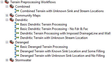
Figure 3 - Toolbox/toolset organization structure for specific terrain preprocessing use cases (Arc Hydro Python/ProTools).
Table 4. Model builder model names for specific terrain preprocessing use cases in Arc Hydro "Terrain Preprocessing Workflows" toolset (Arc Hydro Tools Python.tbx/Arc Hydro Tools Pro.tbx).
| Use Case | Description | Model Builder Name |
|---|---|---|
| 1 | Completely deranged terrain with unknown sink location and no filling of sinks | Deranged Terrain with Known Sink Location and Some Filling |
| 2 | Completely deranged terrain with unknown sink location and some filling of sinks (always needs filling when not keeping all sinks) | Basic Deranged Terrain Processing |
| 3 | Completely deranged terrain with known sink location and some filling of sinks | Deranged Terrain with Known Sink Location and Some Filling |
| 4 | Combined dendritic/deranged terrain with unknown initial sink and stream locations | Combined Terrain with Unknown Sink and Stream Locations |
| 7 | Completely dendritic terrain with unknown stream locations. Starting point is the known filled DEM. | Basic Dendritic Terrain Processing |
| 7 | Completely dendritic terrain with unknown stream locations. Starting point are known flow direction and flow accumulation grids (typical situation for NHDPlus dataset). | Basic Dendritic Terrain - No Fdr & Fac |
| 7 | Completely dendritic terrain with unknown stream locations. Starting point is the raw DEM. | Dendritic Terrain with Unknown Stream Location |
| 9 | Completely dendritic terrain with known stream locations (using user specified streams) and imposing known boundaries (walls). | Dendritic Terrain Processing with Imposed Drainage Line and Wall |
Selected Arc Hydro Terrain Preprocessing Functions
This is a list of Arc Hydro preprocessing functions identified through use cases 1-9. There are other preprocessing functions that are not presented here but might be needed for implementation of additional capabilities.
Table 5. Overview of functions used per use case/workflow.
| Deranged | Combined | Dendritic | |||||||
|---|---|---|---|---|---|---|---|---|---|
| Function \ Use Case | UC1 | UC2 | UC3 | UC4 | UC5 | UC6 | UC7 | UC8 | UC9 |
| Sink Evaluation | X | X | X | ||||||
| Create Sink Structures | X | X | X | X | X | X | |||
| Flow Direction | X | X | X | X | X | X | X | X | X |
| Adjust Flow Direction in Sinks | X | X | X | X | X | X | |||
| Sink Watershed Delineation | X | X | X | X | X | X | |||
| Append Coastal Catchments | X | X | X | X | X | X | X | X | X |
| Assign CatType Attribute to Catchment FC | X | X | X | X | X | X | X | X | X |
| Fill Sinks | X | X | X | X | X | X | X | X | |
| Level DEM | X | X | X | ||||||
| Flow Accumulation | X | X | X | X | |||||
| Stream Definition | X | X | X | X | |||||
| Stream Segmentation | X | X | X | X | |||||
| Combine Stream Link and Sink Link | X | X | X | ||||||
| Drainage Line Processing | X | X | X | X | |||||
| Adjust Flow Direction in Lakes | X | X | X | ||||||
| Catchment Grid Delineation | X | X | X | X | X | X | |||
| Catchment Polygon Processing | X | X | X | X | X | X | |||
| Adjoint Catchment Processing | X | X | X | X | X | X | |||
| Create Drainage Line Structures from Stream Grid | X | X | X | ||||||
| DEM Reconditioning | X | X | X | X | |||||
| Adjust Flow Direction in Streams | X | X | X |
Indirectly called Arc Hydro functions
The above-mentioned preprocessing functions call some additional Arc Hydro functions:
Assign HydroID
Generate From/To Nodes for Lines
Find Next Downstream Line
Function input and output
This section presents inputs and outputs for each listed preprocessing function. For detailed description consult each tool's help.
Sink Evaluation:
Input: Raw DEM
Output: Sink Polygon Feature Class
Output: Sink Drainage Area
Input (optional): Z Factor
Create Sink Structures. This generates DEM-compliant sink elements. HydroID, FeatureID, SinkID, IsSink fields (and potentially others) need to be managed. The input sink polygon FC can have selected set that will be "obeyed":
Input: Raw DEM
Input: Sink Polygon (this can be user digitized deranged polygon or result from "Sink Evaluation" function)
Output: Sink Polygon (jagged poly based on the input polys and selected set. IsSink = 1)
Output: Sink Polygon Grid (what we call now Sink Link Grid)
Output: Sink Point Feature Class
Output: Sink Point Grid
Input (optional): Stream Feature Class (use the TO_NODE of the stream as the sink if the stream ends in the sink poly)
Input (optional): Draft Sink Point Feature Class (use those points as sinks if they fall into the sink poly)
Input (optional): Use Input DEM as Mask
Flow Direction:
Input: DEM
Output: Flow Direction Grid
Input (optional): External Wall Polygon
Adjust Flow Direction in Sinks:
Input: Flow Direction Grid
Input: Sink Point Grid
Input: Sink Polygon Grid
Output: Flow Direction Grid (adjusted)
Sink Watershed Delineation:
Input: Flow Direction Grid
Input: Sink Point Grid
Input: Sink Point Feature Class
Output: Sink Watershed Grid
Output: Sink Watershed Polygon
Append Coastal Catchments. This is an optional step that should be done for larger DEM with large portion of coastal areas - areas defined as not draining into the "streams". This function defines coastal catchments and appends them to the catchment feature class.
Input: DEM Grid
Input: Catchment Grid
Input/Output: Catchment Feature Class
Assign CatType Attribute. This is an optional step. This function assigns CatType attribute to catchment features.
Input/Output: Catchment Feature Class
Input (optional): Drainage Line Feature Class
Input (optional): Sink Point Feature Class
Fill Sinks:
Input: Raw DEM
Output: Filled DEM
Input (optional): Fill Threshold (depth)
Input (optional): Deranged Polygon (sink polygon form "Create Sink Structures")
Input (optional): Use IsSink Field
Level DEM:
Input: Raw DEM
Input: Lake Polygon (in this case sink polygon from "Create Sink Structures" function)
Output: Level DEM
Input (optional): Fill Elevation Field (for this workflow, this is a mandatory field that should contain a "deep burn" elevation (depth))
Input (optional): Fill elevation Offset in Linear Units
Flow Accumulation:
Input: Flow Direction Grid
Output: Flow Accumulation Grid
Stream Definition:
Input: Flow Accumulation Grid
Input: Number of Cells to Define Stream (or area in km2)
Output: Stream Grid
Stream Segmentation:
Input: Stream Grid
Input: Flow Direction Grid
Output: Stream Link Grid
Input (optional): Sink Watershed Grid
Input (optional): Sink Link Grid
Combine Stream Link and Sink Link:
Input: Stream Link Grid
Input: Sink Link Grid (this should be sink point grid)
Output: Link Grid (combined)
Input (optional): Drainage Line Feature Class
Drainage Line Processing:
Input: Stream Link Grid (in this case link grid with streams and sinks)
Input: Flow Direction Grid
Output: Drainage Line Feature Class
Output: Drainage Line Flow Split Table
Adjust Flow Direction in Lakes. This is an optional step if there are lakes that are being drained by the streams (these are NOT sink lakes; sink lake fdr adjustment was done in step 6):
Input: Flow Direction Grid
Input: Lake Polygon Feature Class (note that these are "lake" polygons that are NOT sink lakes)
Input: Stream grid (in this case drainage line grid created by "Crate Drainage Line Structures" function)
Output: Lake Adjusted Flow Direction Grid
Catchment Grid Delineation:
Input: Flow Direction Grid
Input: Link Grid (in this case Link Grid from previous step)
Output: Catchment Grid
Catchment Polygon Processing:
Input: Catchment Grid
Output: Catchment Feature Class
Adjoint Catchment Processing:
Input: Drainage Line Feature Class
Input: Catchment Feature Class
Output: Adjoint Catchment Feature Class
Output: Catchment Flow Split Table
Create Drainage Line Structures:
Input: Raw DEM
Input: Stream Feature Class
Output: Stream Flow Direction Grid
Output: Stream Link Grid
Output: Drainage Line Feature Class
Output: Drainage Line Flow Split Table
Output Edit Point Feature Class
Option: Clean Right Angles
Option: Use Raster Extent
Option: Input Divergence Flag Field
Option: Minimum Stream Length
DEM Reconditioning:
Input: Raw DEM
Input: Stream Link Grid
Input: Number of Cells for Stream Buffer
Input: Smooth Drop in Z Units
Input: Sharp Drop in Z Units
Output: AGREE DEM
Option: Raise Negative Values
Adjust Flow Direction in Streams:
Input: Flow Direction Grid
Input: Stream Flow Direction Grid
Output: Adjusted Flow Direction Grid