Support for Hydrologic Modeling
September, 2020
Download the PDF here
Introduction
Arc Hydro consists of a data model, toolset, and collection of workflows developed over the years to support geographic information system (GIS) implementations specific to water resources. The initial implementation of Arc Hydro was in 2002 with the data model, Arc Hydro book published by Esri Press, and an initial set of about 30 tools. Since then, Arc Hydro has expanded in terms of both tools and workflows as a result of many project applications. There are now more than 300 Arc Hydro tools, and they continue to be expanded based on work in specific implementations.
This document provides an overview of Arc Hydro tools that support hydrologic modeling and describes basic workflows using these tools. We demonstrate a typical approach to preparing GIS data for integration with the Hydrologic Engineering Center Hydrologic Modeling System (HEC-HMS). Integration of Arc Hydro with HEC-HMS was first implemented using HEC-GeoHMS tools and has since evolved for use within ArcGIS Pro. Although this document illustrates Arc Hydro capabilities for export to a specific hydrologic modeling system, the tools are intended to be flexible enough to prepare data for a range of applications. The documentation of and seamless integration with additional hydrologic modeling systems is an active area of Arc Hydro development.
Document History
Table 1. Document Revision History
| Version | Description | Date |
|---|---|---|
| 1 | First version (GLO) | 7/2020 |
| 2 | Minor changes to Preparing Data for HEC HMS Export documentation (GLO) | 9/2020 |
| 3 | Switch order of centroid creation and Hydro Network creation (GLO) | 9/2020 |
Recommended Reading
This is one of several instructional Arc Hydro documents. The following are the other suggested reading, in order of importance:
Arc Hydro - Overview of Terrain Preprocessing Workflows (key tools referenced are available for both 10.X and Pro)
HEC-HMS Documentation (relevant for the specific use case shown)
Solution Overview
The tools discussed in this document are in the Arc Hydro Tools Pro toolbox supporting ArcGIS Pro 2.4 and later. For most of the tools, there are no differences in behavior or functionality Pro and 10.x. However, the model integration tools, Preparing Data for HMS Export and Create HEC-HMS Basin File, are designed specifically for use within Pro 2.4 and later. This document focuses on the ArcGIS Pro version of the tools.

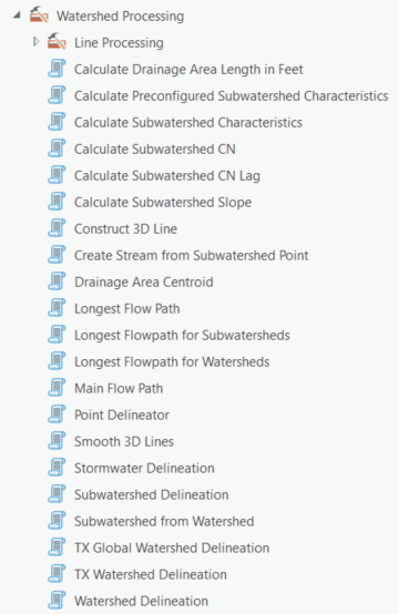
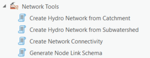
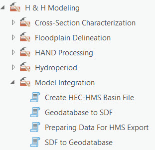
Figure 1. Arc Hydro hydrology-related tools.
Overview of Arc Hydro Tools that Support Hydrologic Modeling
Arc Hydro tools relevant to hydrologic modeling workflows are described in greater detail below. Note that the tools are not presented in the order in which they are used. In addition, not all the tools are used for all workflows.
| Toolset | Step | Tool | Description |
|---|---|---|---|
| Watershed Processing | Watershed Delineation | Watershed Delineation (Interactive) | Delineate local watershed. |
| Watershed Delineation (Batch) | |||
| Subwatershed delineation | Subwatershed from Watershed | Creates Arc Hydro subwatershed polygon and subwatershed point feature classes from Arc Hydro watershed polygon and watershed point feature classes. The input watershed polygon and point feature classes must be attributed according to Arc Hydro standards. | |
| Batch Subwatershed Delineation | Creates Arc Hydro subwatershed polygon and subwatershed point feature classes from Arc Hydro batch point feature class. The input batch point feature class must be attributed according to Arc Hydro standards. | ||
| Basic watershed and Subwatershed characterization | Drainage Area Centroid | Creates a point feature class that represents the centroid of an input drainage area. The centroid can be calculated using one of three methods: center of gravity, halfway distance along the longest flowpath, or where 50% of the drainage area flows to along the given flowpath. | |
| Longest Flowpath | Generates longest flow path features associated to input drainage areas. | ||
| Longest Flowpath for Subwatersheds | Generates longest flow paths for a subwatershed using preprocessed data, (e.g., "Longest Flow Path Adjoint Catchment"), to speed up processing. | ||
| Longest Flowpath for Watersheds | Generates longest flow paths for a watershed using preprocessed data, (e.g., "Longest Flow Path Adjoint Catchment"), to speed up processing. | ||
| Calculate Subwatershed Characteristics | Calculates user specified attribute(s) by applying zonal statistics on user provided characteristics raster(s). One or multiple characteristics can be computed in a single run. | ||
| Calculate Preconfigured Subwatershed Characteristics | Calculates attribute(s) by applying zonal statistics. One or multiple characteristics can be computed in a single run. Input is specified via a configuration file. | ||
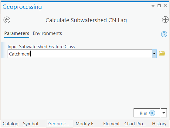
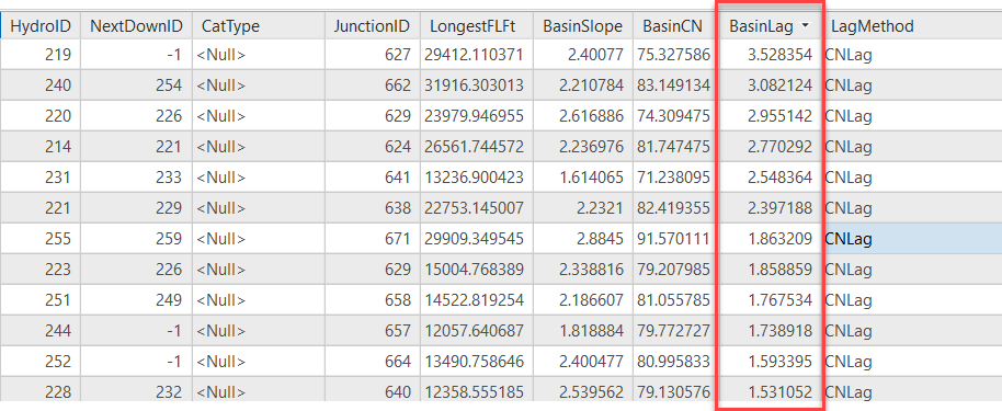
| Calculate Subwatershed CN Lag | Calculates subwatershed lag using NRCS CN basin lag method. Lag is in hours. The following fields need to exist and be populated in the subwatershed feature class: "LongestFLFt", "BasinCN", and "BasinSlope". Output field is "BasinLag". | ||
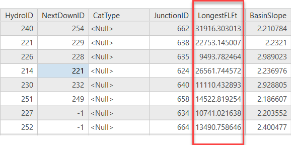
| Calculate Drainage Area Length in Feet | Calculates drainage area length in feet based on the length of area's longest flowpath. Flow path feature class must have field "DrainID" populated with "HydroID" of the matching basin. Output field is "LongestFLFt". | ||
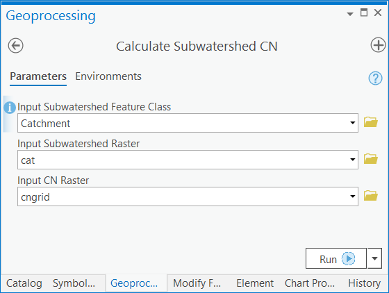
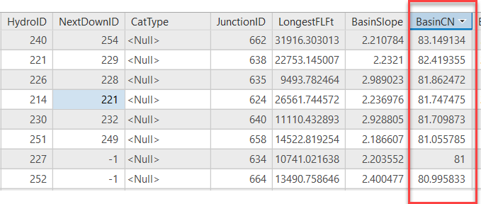
| Calculate Subwatershed CN | Calculates average subwatershed CN based on input CN raster. Output field is "BasinCN". | ||
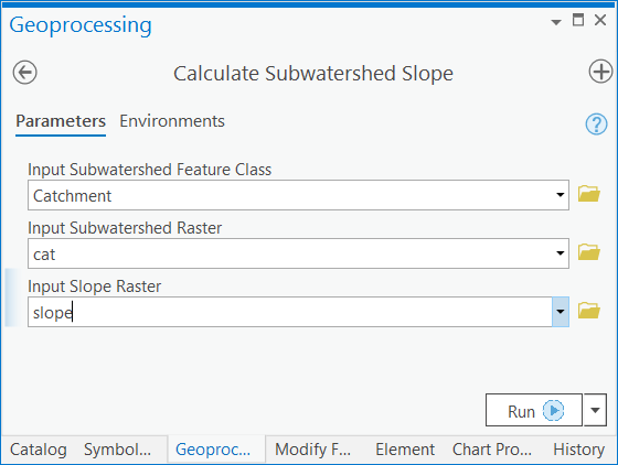
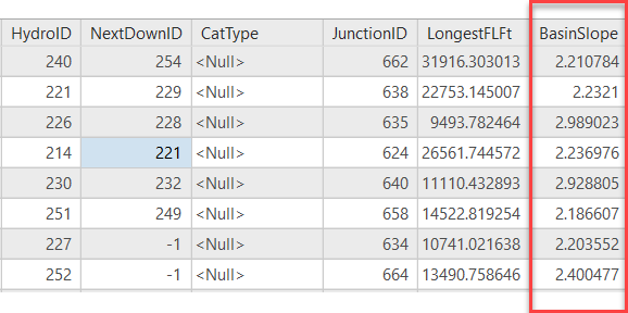
| Calculated Subwatershed Slope | Calculates average subwatershed slope based on input slope raster. Output field is "BasinSlope". | ||
| Point Characterization | Generate Point Connectivity | Generate Point Connectivity | Generates connectivity in watersheds associated to input point features. Using input points and the Flow Direction raster, this tool generates: drainage line features, catchment features associated to the drainage lines, adjoint catchment features, watershed point features, watershed features associated to each point, and stream link raster. |
| Network Tools | Create Network Connectivity | Create Network Connectivity | Creates network connectivity associated to input stream, pipe, inlet, outlet and catchment features using Node/Link features and connectivity. |
| Create Node-Link Representation from Centroids and Subwatershed Outlets (nodes) and Drainage lines (links) | Create Stream from Subwatershed Point | Generates a hydro network (hydro edges and hydro junctions) from drainage lines, catchments, and drainage points. | |
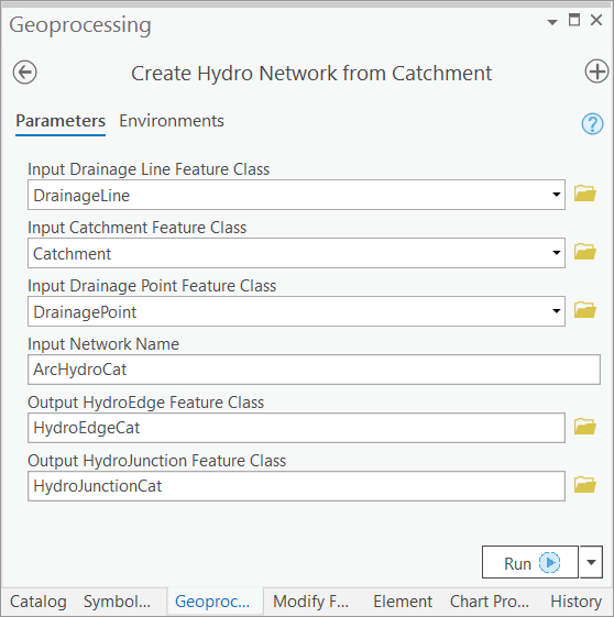
| Create Hydro Network from Catchment | Generates a hydro network (hydro edges and hydro junctions) from drainage lines, catchments, and drainage points | ||
| Create Hydro Network from Subwatershed | Generates a hydro network (hydro edges and hydro junctions) from drainage lines, catchments, and drainage points. | ||
| Generate Node/Link Schema | Generates a node-link schema, where nodes are defined by the centers of basin polygons and by points that represent locations of interest in the model. These points may include basin outlets, river junctions, water intakes and other facilities. | ||
| H & H Modeling, Model Integration | Exporting hydrologic system data to be integrated with hydrologic modeling software | Preparing Data for HMS Export | Prepares basin system data to be exported to a HEC-HMS Basin model file. This tool organizes the data necessary for export into five tables, which are intended to be used as inputs to Create HEC-HMS Basin File. |
| Create HEC-HMS Basin File | Pulls data from the HMS schema tables created using Preparing Data for HMS Export into a basin model file. |
Generic Approach
Hydrologic modeling takes many forms. Arc Hydro tools do not directly perform hydrologic modeling but support it by identifying drainage areas and key landscape characteristics that are the foundation for hydrologic models. Watershed delineation and characterization were part of the first Arc Hydro Tools release in 2002. Simple models, like rational method, can be easily performed within GIS once the watershed and characteristics needed to support the method are derived.
This document explores more complex hydrologic modeling scenarios where simple empirical models are insufficient. For complex models, Arc Hydro prepares the input data to the extent possible and exports the data into the hydrologic model. The hydrologic modeling is performed outside of the GIS. Data requirements in this process will vary with the complexity of the implemented hydrologic techniques. There are a few generic steps that are common to most complex hydrologic models:
Partition the landscape into hydrologic modeling units based on morphologic and hydrologic requirements.
Establish connectivity (i.e., node-link) between hydrologic units.
Characterize hydrologic modeling units.
Prepare model inputs in a model specific format (i.e., model input files).
Steps 1-3 are common for all models. Step 4 will vary from model to model, but the actual content derived in steps 1-3 is the same. This document presents methods for data preparation for Hydrologic Engineering Center's HEC-HMS hydrologic model. Many other hydrologic models can be supported with minimal change to tools in step 4.
The following sections explore specific hydrologic modeling workflows and which tools are used for them. The workflows are documented using build 2.0.191 for ArcGIS Pro.
Overview of an Arc Hydro Hydrology Workflow
We demonstrate an approach for creating a hydrologic data model for HEC-HMS consumption. The approach branches into two common use cases for generating hydrologic units (i.e., catchments or subwatersheds) with varying levels of customization. Although the processes generate a final result specifically targeted to the HEC-HMS modeling system, the approach features standard components:
standard dendritic terrain preprocessing,
landscape tessellation and connectivity generation,
node-link schema generation,
landscape and basin element attribution,
export to a modeling compliant format.
Figure 2 presents this workflow. Only the last component is HEC-HMS specific as it generates a HEC-HMS input file. All other steps would be common to any other node-link based hydrologic model. In the following sections, each step is described in terms of user input, example outputs, and further details. Our example implements the curve number loss method for model setup. Other loss methods supported by HMS and other models can be implemented as well using a combination of standard and Arc Hydro tools. Processing times for executing tools from this approach is documented in [Appendix 4.1].
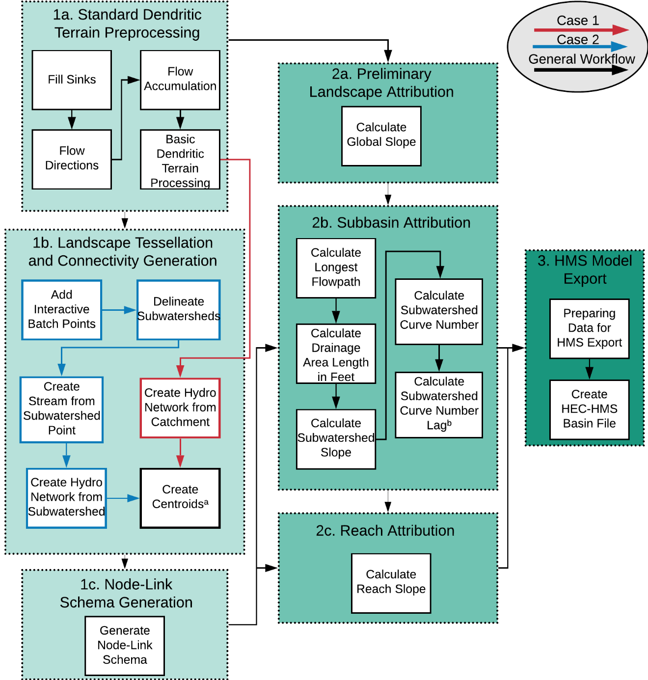
Figure 2. Arc Hydro workflows for hydrologic modeling. After completing the generic processes in part 1a, two use cases for creating the hydrologic network are shown (1b), as well as further schema creation (1c). These case-specific processes produce prerequisite data for attribution of the hydrologic network (2b and 2c) past the standard attribution (2a). Finally, a generic model export is performed, shown here for the HEC-HMS system (part 3).
aWhen following Use Case 1, Arc Hydro catchments, created from Basic Dendritic Terrain Processing, are used directly as the input for Create Centroids. Through Use Case 2, subwatersheds are derived through additional processing.bAt this point, additional subbasin attributes can be derived that are not shown here.1. Standard Dendritic Terrain Preprocessing
While standard dendritic terrain preprocessing is presented here, other morphologies are supported, and their results can be used as input for later steps. Review document "Arc Hydro - Overview of Terrain Preprocessing Workflows" for discussion on other possible terrain processing workflows and select one that matches your conditions the best.
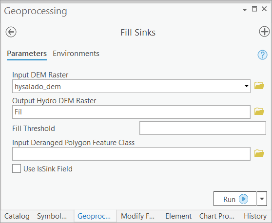
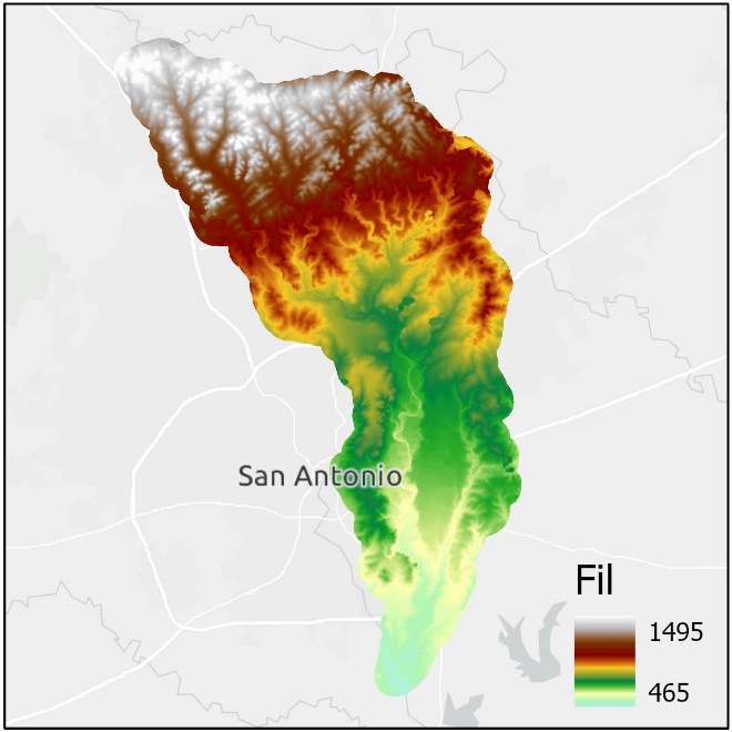
- Fill Sinks
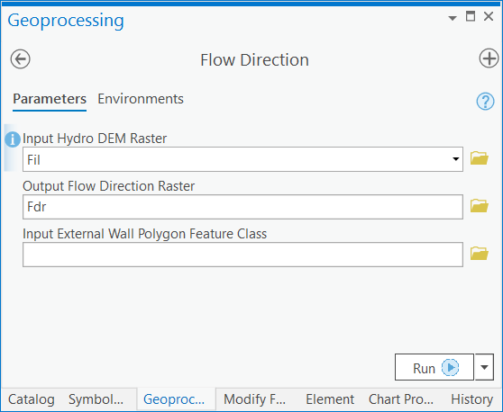
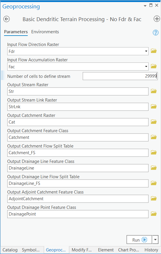
- Flow Direction
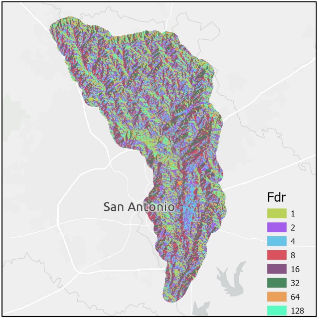
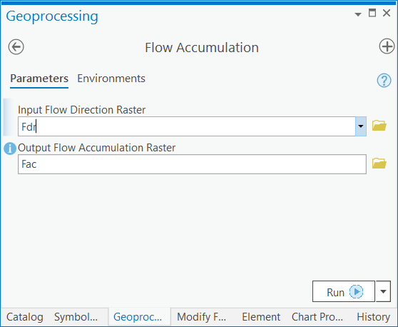
- Flow Accumulation
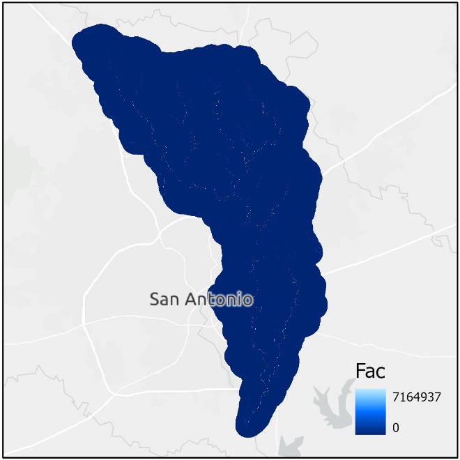
- Basic Dendritic Terrain Processing
Not shown in output: Stream raster, stream link raster, catchment raster, catchment flow split table, and the drainage line flow split table.
2. Landscape Tessellation and Connectivity Generation
Use Case 1: Using Arc Hydro Catchments as HMS Subbasins
Use Case 1 describes the generic approach to the landscape tessellation and connectivity generation phase. The catchments and their related components created from Basic Dendritic Terrain Processing are used directly for subsequent schema generation and attribution. Thus, this approach assumes the outputs from Basic Dendritic Terrain Processing represent the complete set of basin elements of interest for hydrologic modeling.
Create Hydro Network from Catchment

Create centroids
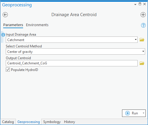

Note: Drainage Area Centroid will populate the JunctionID associated with each centroid if it is present in the Input Drainage Area. For this reason, Drainage Area Centroid must be run after Create Hydro Network from Catchment as tools later in this workflow rely on JunctionIDs being present for centroid features.
Use Case 2: Creating HMS Subbasins from User-Defined Batch Points
Use Case 2 describes an alternative workflow, where subbasins are created from a more specific set of drainage outlet points. This approach is useful when additional areas of interest exist (e.g., gauging stations) and users want to further customize the hydrologic data model.
- Add Interactive Batch Points
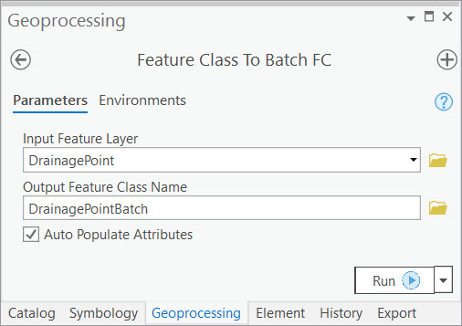

In this example, the user selects a subset of the drainage points feature class to represent the drainage outlets for their specific area of interest. The selected points are exported using the Feature Class to Batch Points tool.
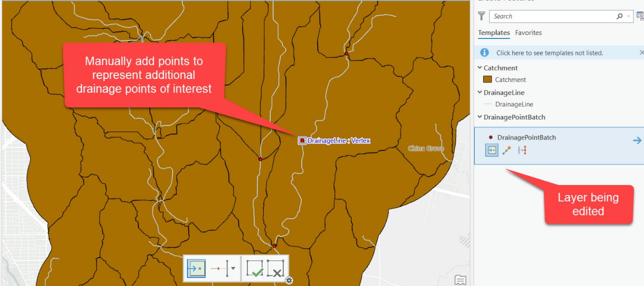
The user then adds additional points along the drainage lines. These
points define additional subbasin outlets of interest in the model and
mimic the splitting capability available in GeoHMS.
Hint: Enable snapping to improve performance of subsequent steps.
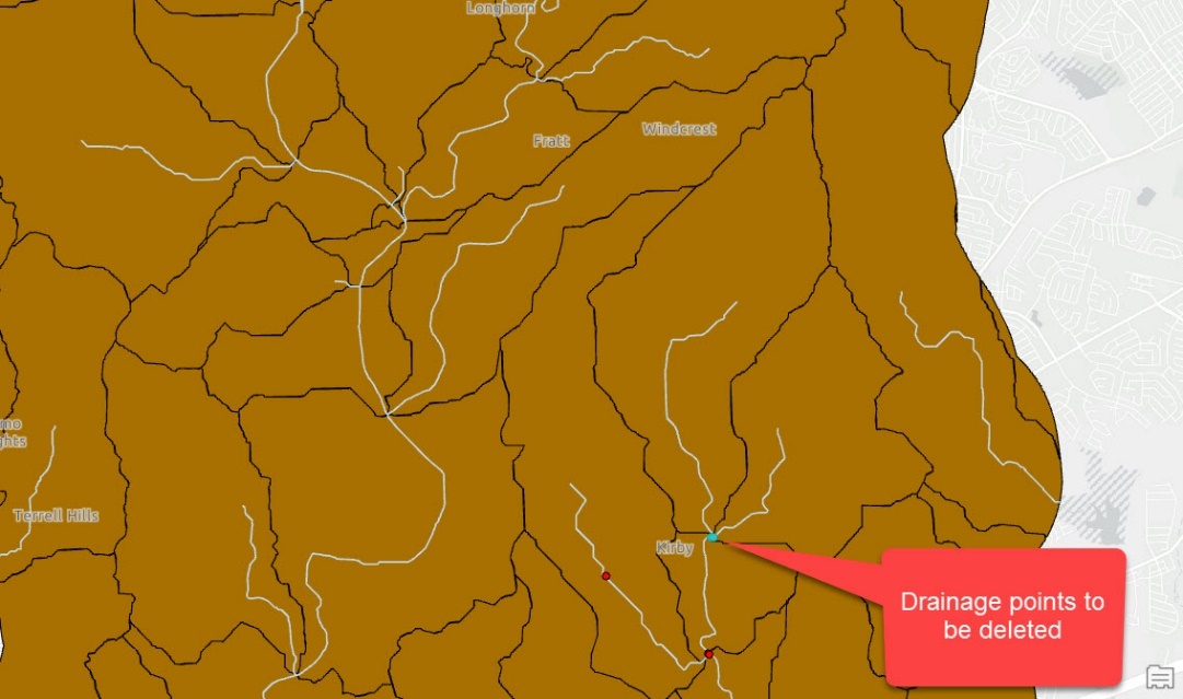
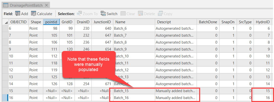
Next, the user deletes two drainage points that correspond to adjacent catchments, leaving a single downstream point that will generalize these drainage areas along with the catchment directly downstream of both. This action mimics the merging capability available in GeoHMS.
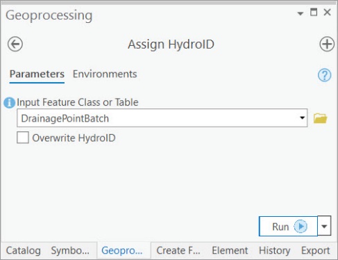
After completing the interactive creation of drainage points, Hydro IDs are assigned to the new features.
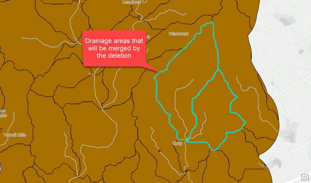
- Delineate Subwatersheds
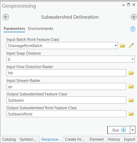
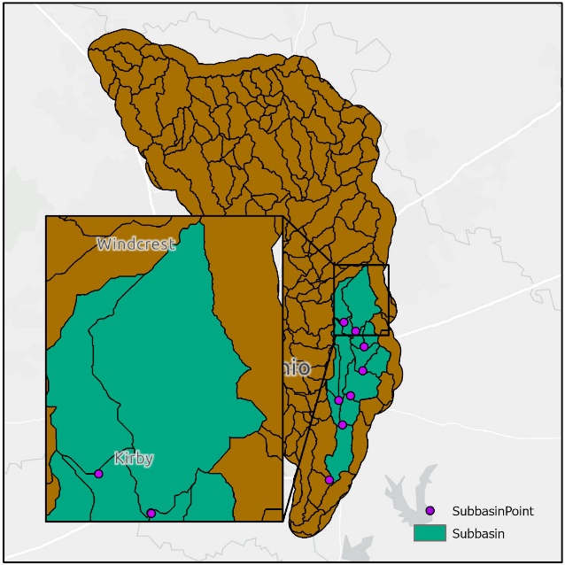
The user can now delineate subwatersheds from the interactive batch points. On the right, the inset map highlights the merged drainage areas resulting from the deletion of drainage points.
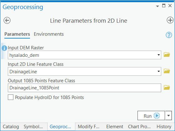
- Create Stream from Subwatershed Point
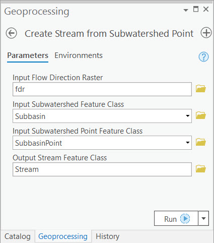

Unlike Use Case 1, where the generic drainage lines created by Basic Dendritic Terrain Processing are applied, user-specific streams are derived for Use Case 2. These features are based on the interactively created batch points ("SubbasinPoint" feature class) and are derived from the Create Stream from Subwatershed Point tool. This tool ensures that flow connectivity between subwatersheds is determined, even if the governing batch points do not fall on a pre-defined drainage line. Note that in following steps, the output stream feature class would replace the drainage line feature class associated with Use Case 1.
- Create Hydro Network from Subwatershed
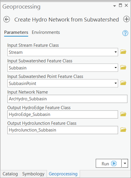
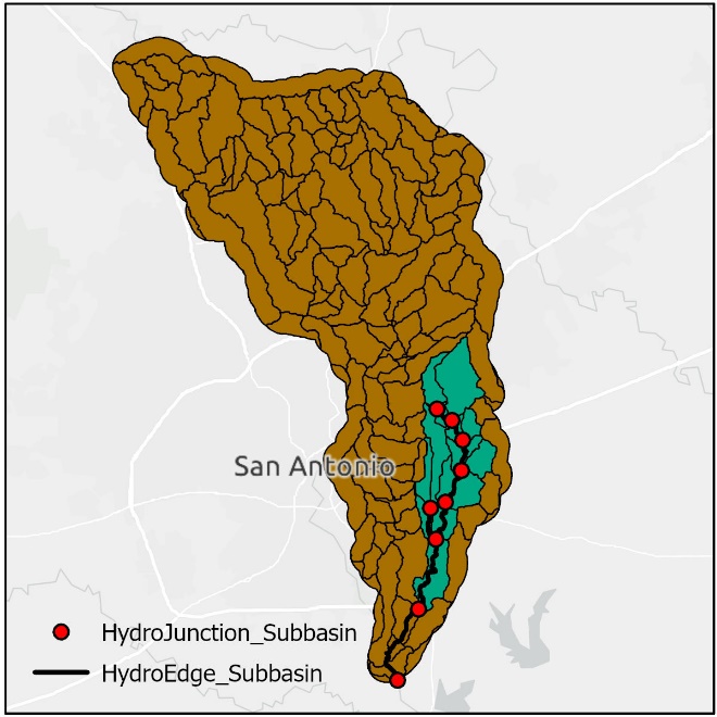
- Create centroids using the same process as shown in Use Case 1
Note: Drainage Area Centroid will populate the JunctionID associated with each centroid if it is present in the Input Subwatershed. For this reason, Drainage Area Centroid must be run after Create Hydro Network from Subwatershed as tools later in this workflow rely on JunctionIDs being present for centroid features.
3. Node-Link Schema Generation
Input data corresponding to Use Case 1 are used until reaching HMS Model Export.
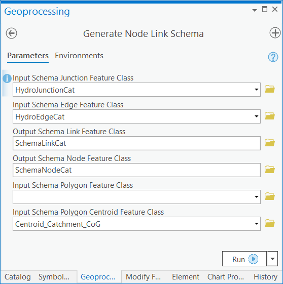
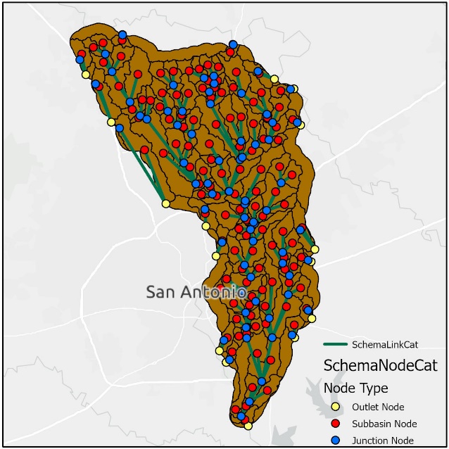
- Generate Node-Link Schema
4. Preliminary Landscape Attribution
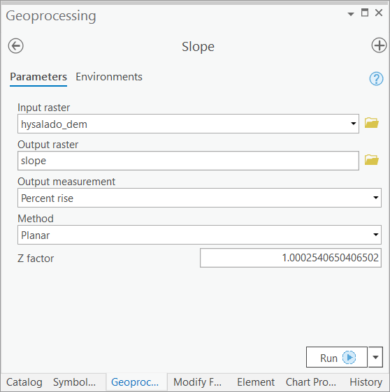
- Calculate Global Slope
5. Subbasin Attribution
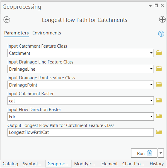
- Calculate Longest Flow Path

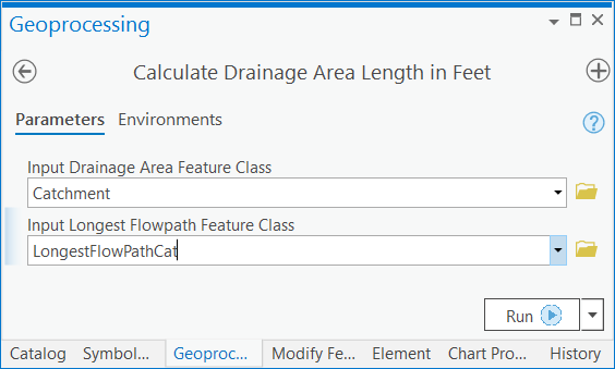
- Calculate Drainage Area Length in Feet
- Calculate Subwatershed Slope
- Calculate Subwatershed Curve Number
- Calculate Subwatershed Curve Number Lag
6. Reach Attribution
- Calculate Reach Slope
7. HMS Model Export
We demonstrate a workflow for integrating Arc Hydro outputs with HEC-HMS. GIS data that follow the Arc Hydro standards can be exported to a format compatible with HMS (i.e., *.BASIN file) using two tools: Preparing Data for HMS Export and Create HEC-HMS Basin File. These tools were developed and tested used HEC-HMS 4.2.1, but the resulting Basin file is compatible with HEC-HMS 4.4.1.
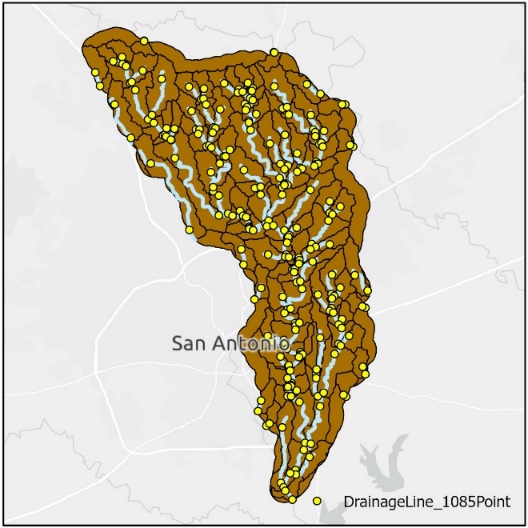
In the following sections, the workflow is demonstrated using a subset of the Use Case 1 data that has been processed through section 3.7, and then further attributed using external user knowledge of the study area (Figure 3).
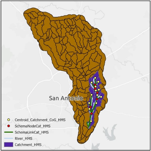
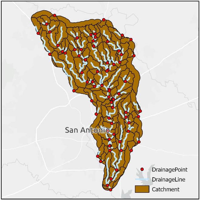
Figure 3. Case study area ("Catchment_HMS") used to demonstrate Arc Hydro's integration with an external hydrologic modeling system, HEC-HMS.
Preparing Data for HMS Export
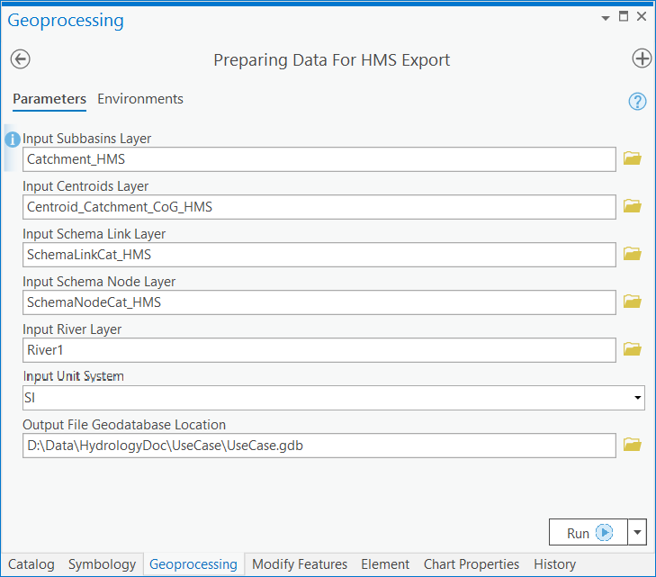
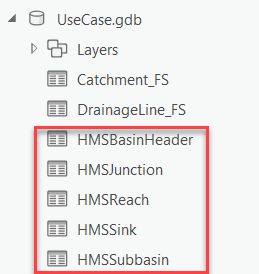
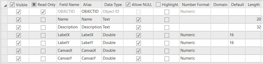
This tool extracts information from input layers created following Arc Hydro standards. The information is organized into five intermediate output tables (right). These tables are created using pre-configured schemas from the Arc Hydro data model. The tool searches the input layers for each field name found in the corresponding Arc Hydro schema table. If a field name is not present in the input layer, default or Null values are used to populate these in the output tables and a warning message alerts the user which atrtibutes fell into this category. Using the preparation steps shown in this document alone will not populate the entirety of the data elements that are ideal for HMS implementation. However, given additional information about one's dataset and area of interest, users can include these data by manually populating the intermediate output tables. Users should reference [Appendix 4.2] for the data elements the BASIN file can contain. This appendix also inlcudes notes for how default values are determined and tips for populating HMS attributes where applicable. Users should also see the HEC-HMS documentation for further details regarding the utility of these data elements in the context of hydrologic modeling.
Note: In most cases, Arc Hydro will assign a default naming scheme to output basin elements (i.e., subbasins, reaches, junctions, sinks). If users want to have control over the unique names assigned to each basin element, they must apply these names to the input layers. Users should not edit the "Name" fields in the intermediate output tables.
Note: The appeneded version of the Use Case 1 dataset includes a River feature class. To repeat this process with the base dataset for Use Case 1, the drainage line feature class would be applied in place of the River feature class. Similarly, the stream feature class from Use Case 2 would replace the River feature class.
Note: Users should clear the created tables from the map view before re-reunning this tool.
- Create HEC-HMS Basin File
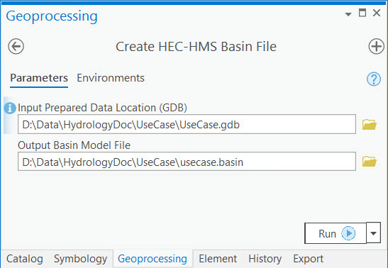
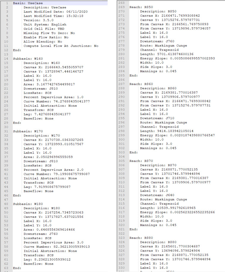
This tool accesses the intermediate HMS tables by searching the input file geodatabase for the default table names (i.e., those pictured in step 1). Data from these tables are organized into *.BASIN file with the format required by HEC-HMS. Note that the example output shown above is populated with minimal Null or default values, as it was derived from a very complete input dataset.
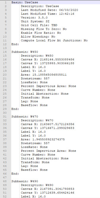
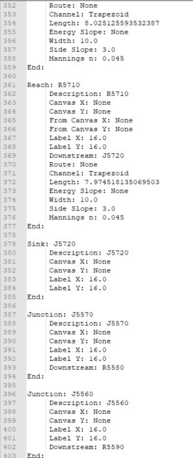
In comparison, the example output below shows an output BASIN file for an incomplete dataset. This example was created using data from Use Case 2, with minimal basin attribution. Despite the default and Null values applied throughout, the BASIN file will successfully load in the HEC-HMS program. However, users would need to gather this missing information before any meaningful hydrologic modeling could be accomplished.
Appendix - Importing the Basin Model File to HEC-HMS gives steps for importing the resulting .BASIN files to the HEC-HMS program.
Appendix
Processing Times
The information in this appendix is provided for reference only. The actual performance will vary greatly depending on the size and complexity of the underlying DEM and function parameters. The numbers provided here are to be used as a relative measure of performance - which functions are "faster" and which are "slower". Remember that raster processing tends to be non-linear for large rasters and that doubling the size of the raster will usually result in more than doubling the time it takes to process it.
The hardware used for processing will also have an impact on the performance. Fast hard-drive (HD) subsystem (preferably SSD) can double the improvement in performance compared to traditional HD. Make sure that both the scratch and permanent storage are pointing to the fast HD. For other processing suggestions, refer to "Arc Hydro - Project Development Best Practices" document.
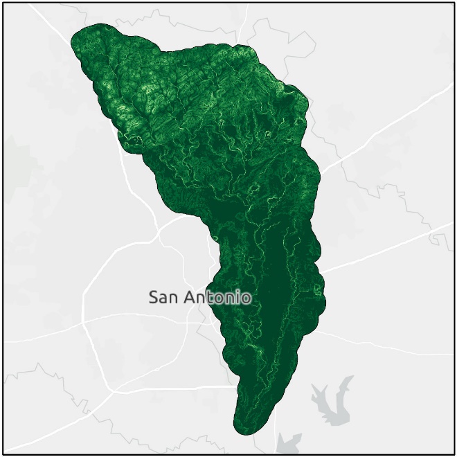
The following results were collected using a machine with 64 GB of RAM. The largest extent of the testing dataset, located in the Salado Creek watershed in San Antonio, TX, included:
10 m DEM with 3,500 columns and 6,000 rows
209 catchments
131 drainage lines
| Tool | Runtime |
|---|---|
| Fill Sinks | 20 seconds |
| Flow Direction | 10 seconds |
| Flow Accumulation | 20 seconds |
| Basic Dendritic Terrain Processing | 2 minutes, 15 seconds |
| Slope | 5 seconds |
| Subwatershed Delineation | 4 minutes (13 drainage points) |
| Drainage Area Centroid (Center of Gravity method) | 15 seconds |
| Longest Flowpath for Catchments | 1 minute, 15 seconds |
| Calculate Subwatershed CN Lag | 10 seconds |
| Calculate Drainage Area Length in Feet | 10 seconds |
| Calculated Subwatershed Slope | 10 seconds |
| Create Stream from Subwatershed Point | 2 minutes, 30 seconds (13 subwatershed points) |
| Create Hydro Network from Catchment | 45 seconds |
| Create Hydro Network from Subwatershed | 3 minutes |
| Generate Node/Link Schema | 30 seconds |
| Preparing Data for HMS Export | 1 minute |
| Create HEC-HMS Basin File | 5 seconds |
Schema Designs for the HMS Export Tables
HMSBasinHeader
Schema
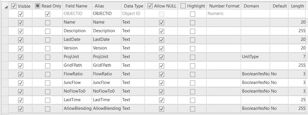
Notes
| Field | Details |
|---|---|
| Name | Default naming is name of the Pro project (watch for weird characters). |
| Description | Default is to copy the Name field. |
| LastDate | Date when the table is created. |
| Version | Hardcoded as the most current version of HMS that is supported for these tools. |
| ProjUnit | Keyword representing the user-selected unit system to apply. |
| GridFpath | N/A for the current implementation. |
| FlowRatio | N/A for the current implementation. |
| JuncFlow | N/A for the current implementation. |
| NoFlowto0 | N/A for the current implementation. |
| LastTime | Time when the table is created. |
| AllowBlending | N/A for the current implementation. |
HMSSubBasin
Schema
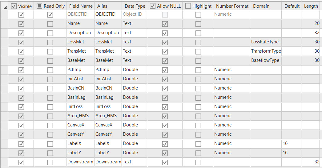
Notes
The Subbasin layer is the primary source for this table. The centroid layer is a secondary source.
| Field | Details |
|---|---|
| Name | Default naming is "W" + (HydroID * 10). |
| Description | Default is to copy the Name field. |
| LossMet | Will be populated using the LossMet field in the Subbasin layer, if it exists. Otherwise, Null. User tip: Refer to the HMS documentation to understand the application of this field and the possible values, then use Calculate Fields to apply the desired value to all features in the subbasin feature class. |
| TransMet | Will be populated using the TransMet field in the Subbasin layer, if it exists. Otherwise, hardcoded as "SCS". User tip: Refer to the HMS documentation to understand the application of this field and the possible values, then use Calculate Fields to apply the desired value to all features in the subbasin feature class. |
| BaseMet | Will be populated using the BaseMet field in the Subbasin layer, if it exists. Otherwise, Null. User tip: Refer to the HMS documentation to understand the application of this field and the possible values, then use Calculate Fields to apply the desired value to all features in the subbasin feature class. |
| PctImp | Will be populated using the PctImp field in the Subbasin layer, if it exists. Otherwise, Null. User tip: If a percent impervious raster is available for the study area (e.g., from the National Landcover Dataset in the US), use "Calculate Subwatershed Characteristics" in the "Watershed Processing" toolset. |
| InitAbst | Will be populated using the InitAbst field in the Subbasin layer, if it exists. Otherwise, Null. User tip: If a percent impervious raster is available for the study area (e.g., from the National Landcover Dataset in the US), use "Calculate Subwatershed Characteristics" in the "Watershed Processing" toolset. |
| BasinCN | Will be populated using the BasinCN field in the Subbasin layer, if it exists. Otherwise, Null. Note, the BasinCN field is calculated in the documented example. User tip: To calculate this field as shown here, a Curve Number grid must be created. This can be derived with knowledge of the landcover for the area of interest. |
| BasinLag | Will be populated using the BasinLag field in the Subbasin layer, if it exists. Otherwise, Null. Note, the BasinLag field is calculated in the documented example. |
| InitLoss | Will be populated using the InitLoss field in the Subbasin layer, if it exists. Otherwise, Null. User tip: If a percent impervious raster is available for the study area (e.g., from the National Landcover Dataset in the US), use "Calculate Subwatershed Characteristics" in the "Watershed Processing" toolset. |
| Area_HMS | New field that is created in the Subbasin layer by the Preparing Data for HMS Export tool. This field stores the subbasin areas using the correct unit system. |
| CanvasX | X coordinate of the centroid for each subbasin. |
| CanvasY | Y coordinate of the centroid for each subbasin. |
| LabelX | In the current implementation, this is hardcoded to 16. |
| LabelY | In the current implementation, this is hardcoded to 16. |
| Downstream | Name of the junction the subbasin is connected to. Using the Arc Hydro schema, this is looked up by: 1. Identifying the schema node (related to subbasin centroid - "NodeA") where FeatureID of the node = HydroID of the subbasin. 2. Identifying the schema node (related to junction - "NodeB") where HydroID of the node = DownElemID of NodeA. 3. Extracting the "Name" attribute of NodeB if it exists. Otherwise, apply the default naming for junctions: J + (10*HydroID of NodeB). |
HMSJunction
Schema
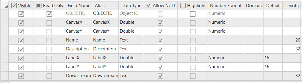
Notes
The Schema Node layer is the primary source for this table. Specifically, the features where SrcType = 2.
| Field | Details |
|---|---|
| Name | Default naming is "J" + (HydroID * 10). |
| Description | Default is to copy the Name field. |
| CanvasX | X coordinate for each schema node. If this field is not present, the geometry of the point is used. |
| CanvasY | Y coordinate for each schema node. If this field is not present, the geometry of the point is used. |
| LabelX | In the current implementation, this is hardcoded to 16. |
| LabelY | In the current implementation, this is hardcoded to 16. |
| Downstream | The downstream element for each junction. This will always be a reach. Using the Arc Hydro schema, this is looked up by: 1. Identifying the schema link (LinkA) where HydroID of the link = DownElemID of the node. 2. Extracting the "Name" attribute of LinkA if it exists. Otherwise, apply the default naming for reaches: "R" + (10 * HydroID of LinkA). |
HMSReach
Schema
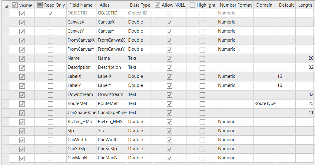
Notes
The Schema Link layer is the primary source for this table, specifically the features where LinkType = 2. The Schema Node layer and the River layer are secondary sources.
| Field | Details |
|---|---|
| Name | Default naming is "R" + (HydroID * 10). |
| Description | Default is to copy the Name field. |
| RouteMet | Will be populated using the RouteMet field in the Subbasin layer, if it exists. Otherwise, hardcoded as "Muskingum Cunge". User tip: Refer to the HMS documentation to understand the application of this field and the possible values, then use Calculate Fields to apply the desired value to all features in the subbasin feature class. |
| ChnShapeKine | Will be populated using the ChnShapeKine field in the Subbasin layer, if it exists. Otherwise, hardcoded as "Trapezoid". User tip: Refer to the HMS documentation to understand the application of this field and the possible values, then use Calculate Fields to apply the desired value to all features in the subbasin feature class. |
| RivLen_HMS | New field that is created in the Schema Link layer by the Preparing Data for HMS Export tool. This field stores the reach lengths using the correct unit system. |
| Slp | Will be populated using the Slp field in the River layer, if it exists. Otherwise, Null. User tip: This field should be populated after executing the step "Calculate Reach Slope" step. |
| ChnWidth | In the current implementation, this is hardcoded to 10. User tip: Refer to the HMS documentation to understand the application of this field and the possible values, then use Calculate Fields to apply the desired value to all features in the subbasin feature class. |
| ChnSdSlp | In the current implementation, this is hardcoded to 3. User tip: Refer to the HMS documentation to understand the application of this field and the possible values, then use Calculate Fields to apply the desired value to all features in the subbasin feature class. |
| ChnManN | In the current implementation, this is hardcoded to 0.045. User tip: Refer to the HMS documentation to understand the application of this field and the possible values, then use Calculate Fields to apply the desired value to all features in the subbasin feature class. |
| FromCanvasX | X coordinate of the reach FROM node. If this field is not present, the correct node is looked up using the Arc Hydro schema by: 1. Identifying the upstream schema node (FromNode) where HydroID of the node = FromNodeID of the reach. 2. The X coordinate of FromNode is used. |
| FromCanvasY | Y coordinate of the reach FROM node. If this field is not present, the correct node is looked up using the Arc Hydro schema by: 1. Identifying the upstream schema node (FromNode) where HydroID of the node = FromNodeID of the reach. 2. The Y coordinate of FromNode is used. |
| CanvasX | X coordinate of the reach TO node. If this field is not present, the correct node is looked up using the Arc Hydro schema by: 1. Identifying the downstream schema node (ToNode) where HydroID of the node = ToNodeID of the reach. 2. The X coordinate of ToNode is used. |
| CanvasY | Y coordinate of the reach TO node. If this field is not present, the correct node is looked up using the Arc Hydro schema by: 1. Identifying the downstream schema node (ToNode) where HydroID of the node = ToNodeID of the reach. 2. The Y coordinate of ToNode is used. |
| LabelX | In the current implementation, this is hardcoded to 16. |
| LabelY | In the current implementation, this is hardcoded to 16. |
| Downstream | The downstream element for each reach. This will always be a junction. Using the Arc Hydro schema, this is looked up by: 1. Identifying the schema node (NodeA) where HydroID of the node = DownElemID of the reach. 2. Extracting the "Name" attribute of NodeA if it exists. Otherwise, apply the default naming for junctions: "J" + (10 * HydroID of NodeA). |
HMSSink
Schema
Notes
The Schema Node layer is the primary source for this table. Specifically, the features where DownElemID = -1.
| Field | Details |
|---|---|
| Name | Default naming is "J" + (HydroID * 10) |
| Description | Default is to copy the Name field. |
| CanvasX | X coordinate for each schema node. If this field is not present, the geometry of the point is used. |
| CanvasY | Y coordinate for each schema node. If this field is not present, the geometry of the point is used. |
| LabelX | In the current implementation, this is hardcoded to 16. |
| LabelY | In the current implementation, this is hardcoded to 16. |
Importing the Basin Model File to HEC-HMS
The approach below outlines the method for importing the basin model file created in section 3.7 into HEC-HMS.
- Create a new project in HEC-HMS.
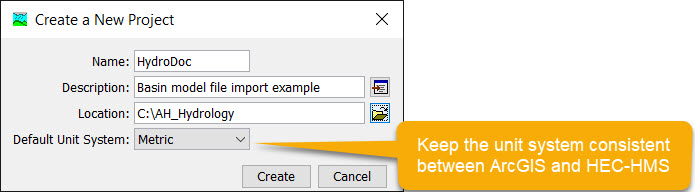
Note: The units chosen here should be consistent with those used in Preparing Data for HMS Export
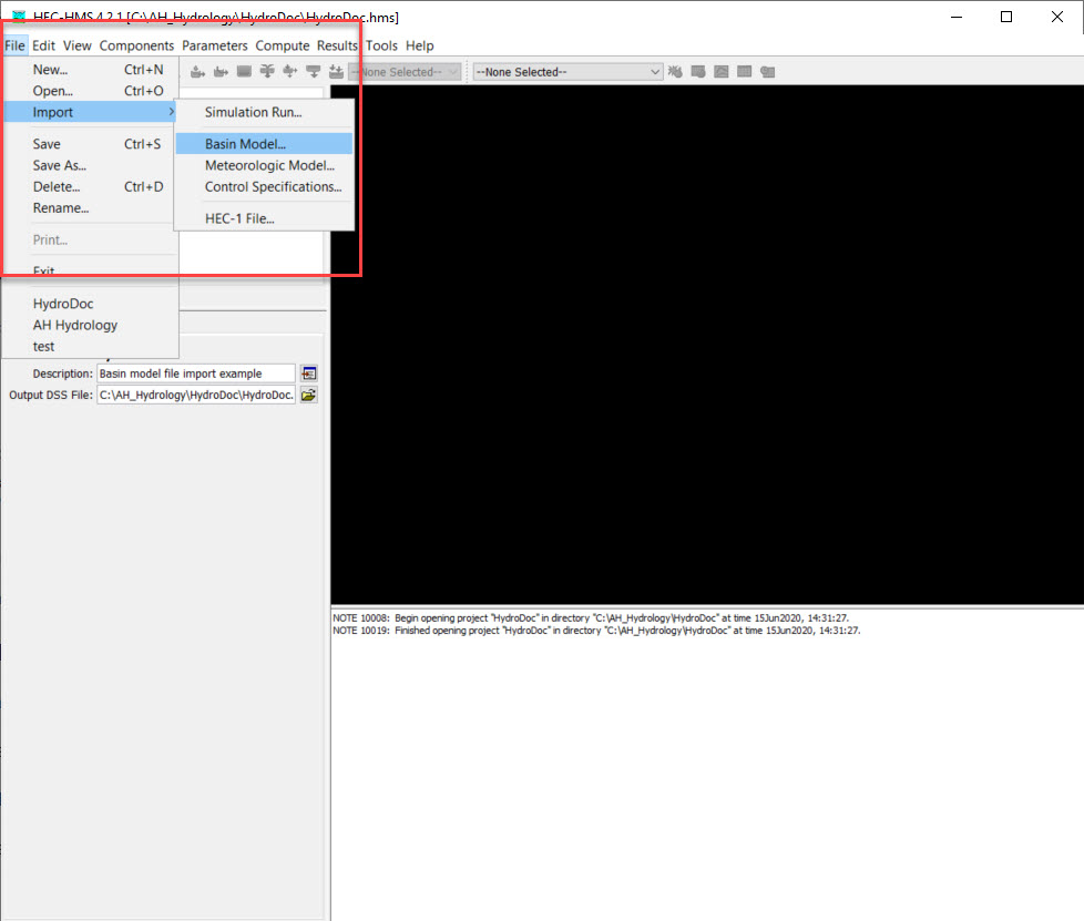
- File > Import > Basin Model and select your .BASIN file
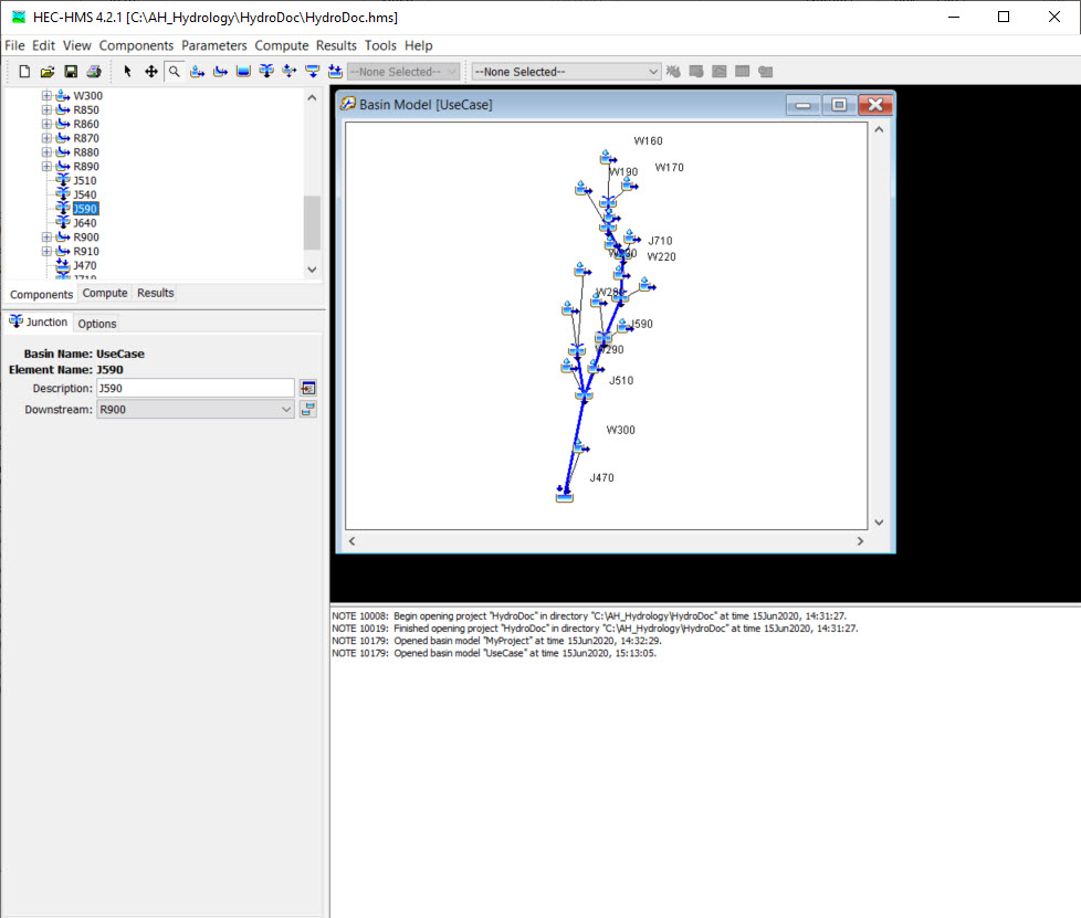
- The basin elements described in the .BASIN file should load as icons in the HMS schematic.
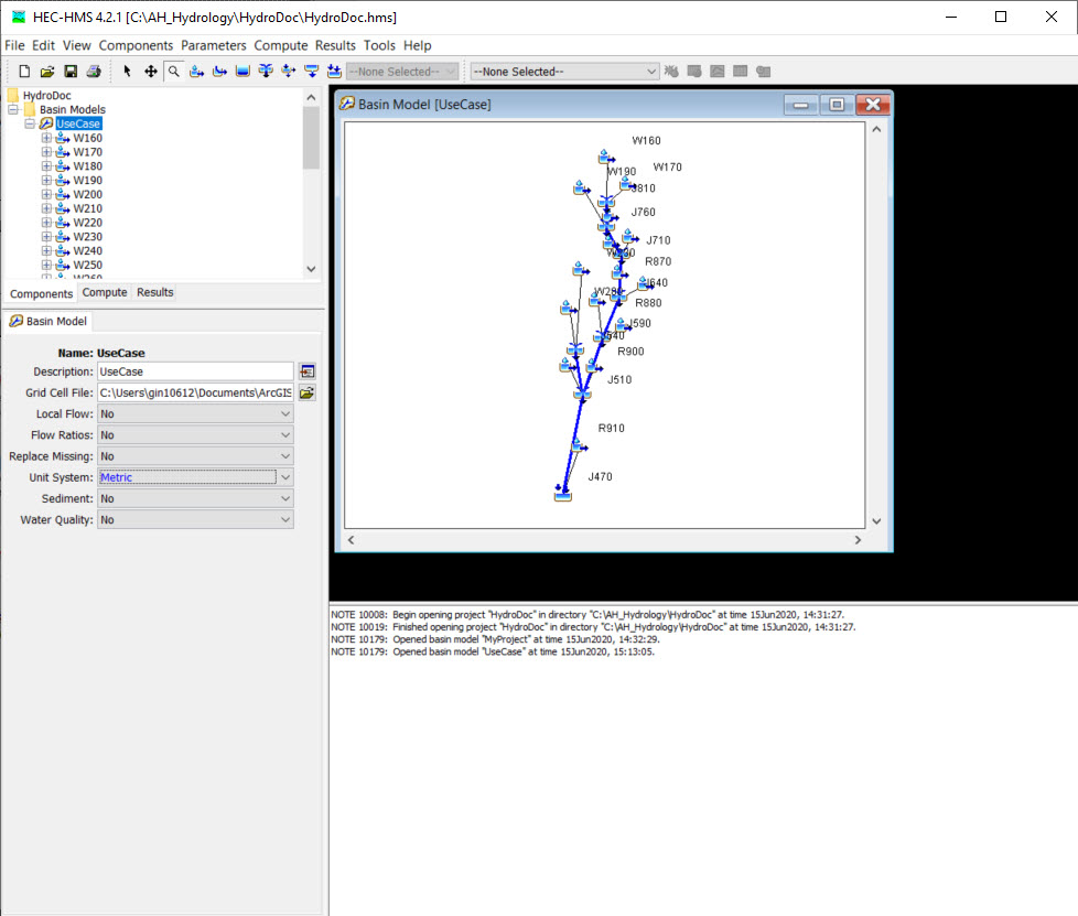
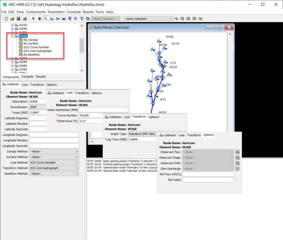
Attributes for each element will also be reflected in the Components interface. See the information extracted for basin W260 and it's downstream element, junction J590, below.